
HOLYKELL UF2000 Series User manual


Contents
1. Products Categories.................................................................................................................. 2
1.1 Composition of Ultrasonic flow meter .......................................................................... 2
1.2 Types of Converters ....................................................................................................... 2
1.3 Types of Flow/Temperature Transducers ....................................................................... 3
2. Check Components................................................................................................................... 3
3. Measuring Diagrams ................................................................................................................ 4
4. Converter Installation and Wiring Diagram ............................................................................. 5
4.1 Separated Mounting ....................................................................................................... 5
4.2 Fix mounting .................................................................................................................. 8
4.3 Module type ................................................................................................................... 9
5. Transducer Introduction and Wiring Diagram ....................................................................... 10
5.1 Clamp on type transducer.............................................................................................. 10
5.2 Insertion type transducer .............................................................................................. 11
5.3 Inline type transducer ................................................................................................... 12
6. Display and Operation ............................................................................................................ 13
6.1 Display and keyboard.................................................................................................... 13
6.2 Operation ...................................................................................................................... 13
6.3 Menu Details ................................................................................................................ 14
6.4 Quick setup of measured parameters ........................................................................... 21
7. Transducers Installation ......................................................................................................... 22
7.1 Choose installation points ............................................................................................ 22
7.2 Clamp on transducer Installation ................................................................................. 24
7.3 Insertion type transducer installation ........................................................................... 27
7.4 In-line type transducer installation .............................................................................. 32
7.5 Check Installation ........................................................................................................ 33
8. Finish Installation................................................................................................................... 34

1
Welcome to use the new generation ultrasonic flow meter made of our patented technology.
UF2000 Series Ultrasonic Flow/Heat Meters utilize the transit-time principle to measure the
velocity of relatively clean liquids in full pipes.
The purpose of this guide is to provide installation procedures and basic operating instructions for
UF2000 Series Ultrasonic Flow/Heat Meters.
Installation Procedure
1. Products Categories
1.1 Composition of Ultrasonic flow meter
Ultrasonic Flow meter = Converter + Transducer
Ultrasonic Heat meter = Converter + Transducer + Temperature transducer
1.2 Types of Converters
Items
Separated Mount
Fix Mount
UF2000F
Module type
UF2000M
Wall Mount
UF2000B
Wall mount
UF2000SW
Panel Mount
UF2000SS
Explosion proof
UF2000SD
Picture
1.3 Types of Flow/Temperature Transducers
Check Com
p
onents Choose Installation Points Set Parameter
Connection of
Converter and transducer
Transducer Installation
Check the installation
Converter Installation
Complete

2
Flow Transducer Picture Model Measuring range Temperature
Clamp on
TS-2 (small) DN32-65
-30 ~ 90℃
TM-1 (medium) DN80-400
TL-1 (large) DN450-1000
High temp.
Clamp on
TS-2-HT (small) DN32-65
-30 ~ 160℃
TM-1-HT (medium) DN80-400
TL-1-HT (large) DN450-1000
Insertion
TC-1 (standard) DN80-6000 -30 ~ 160℃
TC-2 (extended)
TP-1 (parallel) DN200-6000
Inline Standard DN15-1000 -30 ~160℃
Temperature
Transducer
Picture Model Measuring
range
Temperature Cutoff water
Clamp on CT-1 ≥ DN50 -40 ~ 160℃No need
Insertion TCT-1 ≥ DN50 -40 ~ 160℃Need
Insertion
under pressure PCT-1 ≥ DN50 -40 ~ 160℃No need
Insertion
small sizes SCT-1 < DN50 -40 ~ 160℃Need
2. Check Components
1. Please check you have all the components in the order.
2. All codes on the converter and transducers should be matched. They are used in sets.
Transducer Codes Transducer Codes on Converter

3
3. Measuring Diagrams
3.1 Separated Mounting
Clamp on Insertion Inline
Note: Mounting of UF2000SS and UF2000SD are in the same way.
3.2 Fixed Mounting
Clamp on Insertion Inline
3.3 Module type
Clamp on Insertion Inline
Temperature can be measured by connecting PT100 temperature transducer on both supply
and return pipes.
4. Converter Installation and Wiring Diagram

4
4.1 Separated Mounting
UF2000B Installation Instruction
Wall mounting: Fix the converter with 4 Φ6 expansion bolts or normal nails.
DIN-rail mounting by using rail fixing clamps.
DIN-rail mounting by using PCB bracket

5
Converter of UF2000B can be installed on the wall or in distribution box and explosion-proof
box
UF2000B Wiring Diagram
UF2000SW and UF2000SD Installation Instruction

6
Thickness: 75mm Thickness: 165mm
UF2000SW and UF2000SD Wiring Diagram
UF2000SS Installation and Wiring Diagram
Explosion-proof grade: DⅡBT5
Fix the converter with 4 Φ8expansion bolts.
Wall mounting: Fix the converter
with 4 Φ6 expansion bolts.

7
4.2 Fix mounting
The converter is generally installed on the pipeline, sometimes installed on the wall of a well to
avoid water immersion.
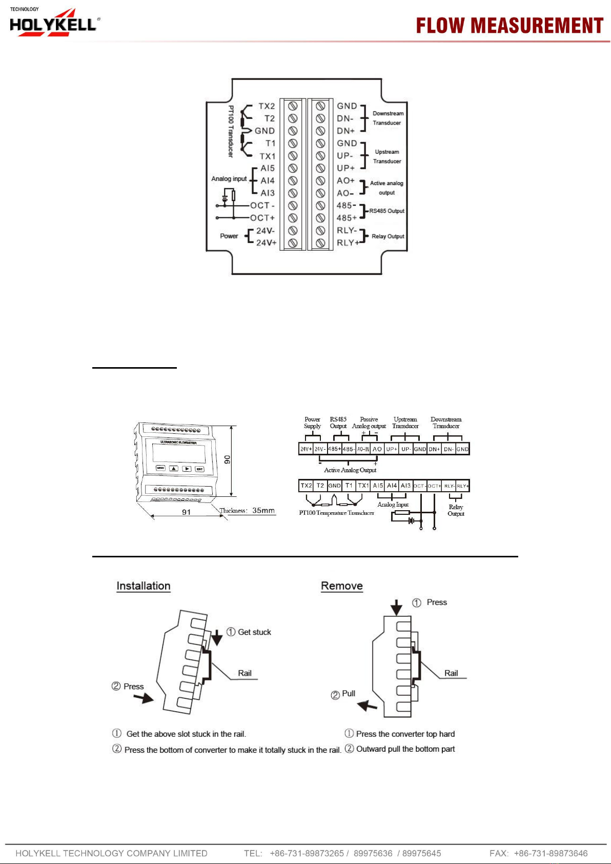
UF2000F Wiring Diagram
8
Open the back cover and complete the wiring. To avoid leaking, please tighten the water joint and
screws of the back cover after wiring. Be sure not to open the front cover.
4.3 Module type
This manual suits for next models
6
Table of contents
Other HOLYKELL Measuring Instrument manuals


