Hix R2R User manual
CONTENTS
Receiving & Installation .................................................................................................... 2
Startup .............................................................................................................................. 3
Time & temp. Settings ....................................................................................................... 4
Loading labels ................................................................................................................... 5
Sensor Setting .................................................................................................................. 7
Operation........................................................................................................................... 9
Transfer Application ........................................................................................................ 10
Troubleshooting................................................................................................................11
Warranty .......................................................................................................................... 12
For Customer Service, Call 1-800-835-0606
or Visit www.hixcorp.com
BEFORE warranty repair you MUST get Prior Authorization:
Call 1-800-835-0606
R2R
Reel to Reel Care Label Heat Press
OWNER’S MANUAL
70594 RV G_120820
2
RECEIVING & INSTALLATION
SHIPPING OR RETURNS
NOTE: Save all of your shipping/packing materials.
DO NOT RISK COSTLY SHIPPING DAMAGE!
SHIP ONLY IN ORIGINAL BOX.
1. Place in original crate.
2. Fasten machine to shipping base with bolts provided.
3. Make sure crate top is securely fastened to base
UNPACKING
Remember to save all packing materials - including box, liner and board. You may need
these for shipping your machine or if a repair is necessary in the future.
INSPECTION
Inspect your machine for hidden shipping damage. Contact the delivery company immedi-
ately, should you nd damage.
INSTALLATION
NOTICE: These machines are heavy, utilize team lifting and
lift with your legs when placing the machine.
1. Remove shipping straps and bolts.
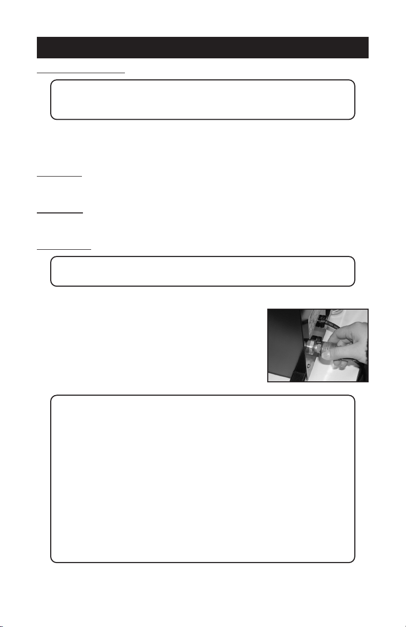
2. Supply a clean (void of oils) and dry (void of water) air
source of 70 P.S.I. (6.8-8.5 bar) to the 3/8” NPT air inlet
located on the back of the machine. Requires 4 CFM.
NOTE: Itisstronglyrecommendedthatanexternalairlterandwatertrap
be installed at the machine’s air inlet connection. Compressed
airisdirty.Ithas‘stu’,primarilymoisture,residuesfromoiland
smoke and whatever else is in the air. Compressors or ‘shop air’
mayhavelteredairand/oran“AIRDRYER”afterthecompressor.
IFyourairisnotlteredanddried,YOUMUSTFILTERTHEAIR
andREMOVETHEWATERand‘stu’FROMTHEAIR,before
putting it in most air operated machines, including our press.
There are small valves and ports that can become blocked from
moisture and residue in compressed air, causing your press to
malfunction.Anexternalairlterandwatertrapmustbeinstalled
atthemachine’sairinletconnection,ifyourairisnotltered.
Damage to the machine’s internal air operated components can
occur that will not be covered under warranty. Combination
airlter/watertrapsareavailableatanymajorhardwarestore
or may be purchased directly from HIX (part #71145).
3
STARTUP
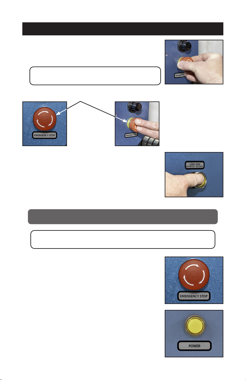
1. Set pressure Turn Knob below air gauge right to increase
pressure. Left to decrease pressure.
NOTE: Air pressure will not decrease until machine
cycles. Set starting pressure to 40-50 PSI.
2. Push Emergency stop button.
3. Make sure Load/Run button is in the “out” (Load) position.
(Press and release to change button position)
4. Plug the machine into the correct grounded electrical outlet.
WARNING: When using an extension cord, use 12 or 14 ga. - 3
conductor. Maximum length, 25’ (7.762 m).
ATTENTION: Utiliser des ralonges d’au moins 12 à 14 ga - 3
phases; longueur maximale de 7.7 mètres.
5. Now rotate Emergency stop button to the right (clockwise)
to release.
6. Push Yellow power button to power on/o the press.

4
TIME & TEMP. SETTINGS
1. To change or set the temperature, press the menu button on the digital control. The light
next to “TEMP” will light. Press the up ▲, or down ▼, button to your desired setting.
2. To change or set the time, press the menu button on the digital control. The light next to
“TIME” will light. Press the up ▲, or down ▼, button to your desired setting.
3. When you have your desired settings press the menu button a third time to lock in your
settings otherwise the previous settings will still be used.
4. Wait for the machine to reach your preset temperature by monitoring the display tem-
perature until it matches the set temperature.
5. Daily cycle is displayed by holding the up key while powering up. It will continue to dis-
play counts (up to 9999) while the up key is pressed. When the key is released it goes
to regular mode.
5
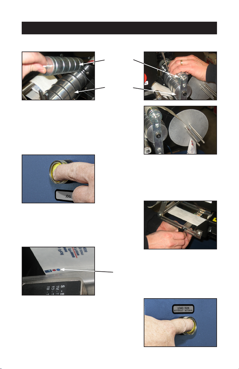
LOADING LABELS
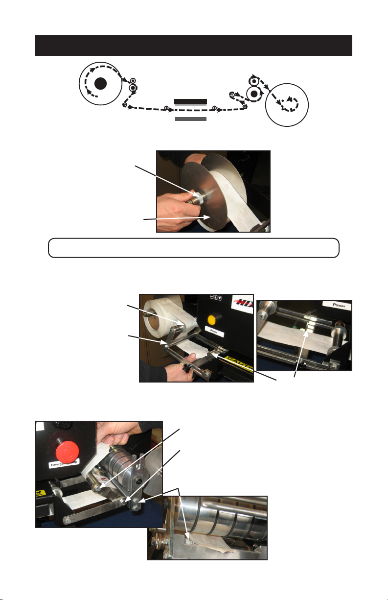
1. Remove Reel Quick Knob and reel face ange (non motor side).
NOTE:QuickKnobscanbeslidoafterrotatingapproximatelyoneturn.
2. Load full reel on supply side (non motor side)
3. Feed Label over top guide rod, under elbow rod and over the sensor.
4. Continue web underneath heat platen and underneath right elbow web guide. Feed
over top guide rod and through slot in drive roller mount.
REEL QUICK KNOB
REEL FACE FLANGE
TOP GUIDE ROD
ELBOW ROD
SENSOR
RIGHT ELBOW WEB GUIDE
TOP GUIDE ROD
DRIVE ROLLER MOUNT
FEED
REEL
HEAT PLATEN
LOWER PLATEN
TAKE-UP
REEL
6
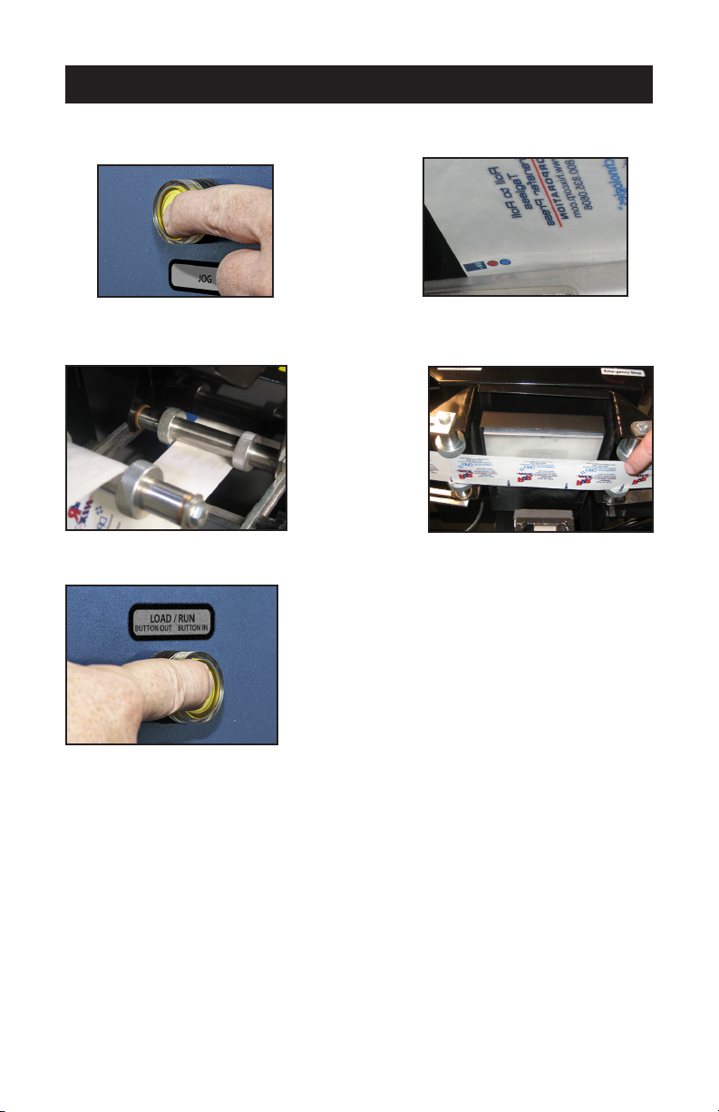
LOADING LABELS
5. For eective web tracking labels should be fed between drive roller and pinch roller
then back over top of pinch roller.
6. Simply place lead edge of label web between four
ngers of take up real and let hang free.
7. Take up slack by pressing and releasing Jog but-
ton on left side of control box.
8. Set sensor position and sensitivity. (see sensor
settings)
9. Position label on platen then move sensor to align
its light beam on the index mark.
10. Push Load/Run button in to set it to Run mode.
INDEX MARK
PINCH ROLLER
DRIVE ROLLER
7
SENSOR SETTING
1. Jog label by depressing and releasing the Jog button to move the label index mark
such that the light beam is aimed on the Index mark.
2. Reposition guides on guide rod to maintain front to rear centering of label. Do not adjust
left to right position at this time.
3. Depress Load/Run button to the “out” position or Load mode
4. Position the sensor light beam onto the index mark printed on the label web by pressing
the “Jog” button.
5. Press and hold the “Dynamic” push bottom (located on the bottom side of the sensor
- closest to the operator) for about 2 seconds until the light beam changes color to a
Tri-Color beam (Green, Red, Blue). Continue to hold the “Dynamic” push button in.
6. While holding the “Dynamic” push button in, pull the light beam o the index mark, onto
the paper only - hold there for 1 second, then put the beam back onto the index mark -
hold there for 1 second, back o the index mark for 1 second then back onto the index
mark for 1 second - then Release the “Dynamic” push button while the beam is shining
on the index mark.
7. The sensor light will return to a “Green” color and is now trained.
8
SENSOR SETTING
8. Put machine in Load/Run (button in) and activate the two optical control switches, the
label will advance to next index mark and stop. Position label front to rear if necessary
(Step 2 of sensor setting) and right to left on lower platen, using jog button.
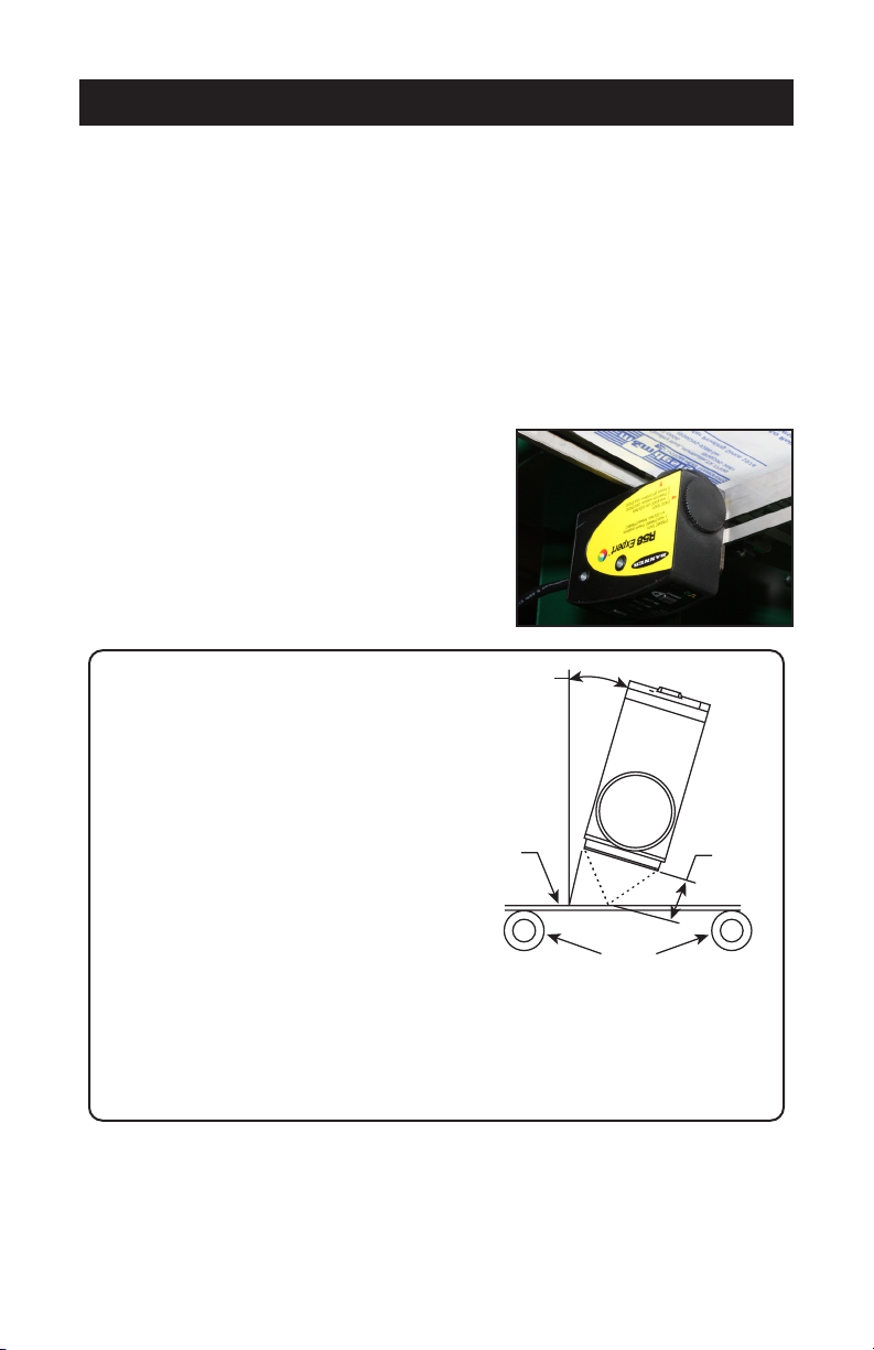
9. Now adjust position of sensor head such that the
light beam is just above the Index mark (approx.
3mm) and tighten.
NOTE: When sensing an index
mark on a reflective (shiny)
material, mount the sensor
at approximately 15° off
perpendicular to the material’s
surface to minimize strong
directreectionsandallowthe
sensor to discern the relatively
small optical contrast oered
bydierencesincolors.
When sensing an index mark
on a clear material, position
a reflective surface directly
behind the clear material to
return light to the sensor. Most
clear materials are also shiny;
it is important to include a 15°
skew angle when sensing clear
materials.
Approximately 15°
Tr
ansparent or
Opaque Reflective
Web Material
Guide Rollers
Mount the sensor at approximately 15° from perpendicular to
the transparent and opaque reflective materials
Focus Distance
3 mm - 10 mm
FOR FURTHER SENSOR INSTRUCTIONS, SEE
INCLOSED BANNER R58E SERIES EXPERT™
REGISTRATION MARK SENSOR MANUAL

9
OPERATION
1. Visually check and conrm label is in centered position.
NOTE: If the label is NOT centered, repeat sensor setting
2. Position Garment into desired position
3. Place nger in each optical control switch, heat head will come down and then rise after
set time, take up roll will automatically index to next label.
WARNING:Keephandsandngersclearofthepressingareaatalltimes
topreventaccidentalburnsorcrushingofngersorhand!
WARNING: DO NOT remove any safety guards or operate this
equipment in a manor not intended by the manufacturer.
WARNING:
For use with roll-to-roll transfers only.
DO NOT use with single cut transfers.
! !

10
TRANSFER APPLICATION
Whenyoufailtomakeasuccessfultransferyoucanwonder,“Isitthemachine’s
fault,orthetransfer,wrongsettingsorwhat”?
FIRST, THE BASICS:
1. Be sure to set the heat transfer machine to the transfer manufacturer’s recommended
Temperature, Time and Pressure settings. If you don’t have these specications, con-
tact your transfer supplier for this information and any other special application instruc-
tions as many of the new “High Tech” transfers require signicantly dierent settings
and/or application techniques than those from years past.
2. When you start up your press for the rst time each day, preheat the pad for a minute.
If the press has sat for 3-5 minutes without use, be sure to “preheat” the pad for 10-15
seconds before loading the shirt or making the rst transfer.
3. Be sure the T-shirt fabric is void of any moisture which can reduce the chance of a suc-
cessful transfer.
4. With all of the above recommendations, try making a transfer.
5. If successful, great! You are on your way to making some serious money with your
transfer machine!
6. If you have an area that isn’t transferring completely or as you would like it to, follow
these steps to determine the problem.
• Try increasing the pressure on the machine by 10-20%
• Recheck your temperature required and the press readout. You may want to in-
crease the temperature 10 degrees.
• Try increasing the application time by 2-4 seconds
• If after trying these things there is still a “specic” area (say over in one corner of
the transfer) that isn’t coming out as you would like it to, then try the same type
transfer on a scrap shirt but rotate the transfer 180 degrees (changing the failure
location) If after doing this the problem area is in the same physical location on
the machine, then you probably have a problem with the pad or possibly a warped
platen if the machine has ever overheated severely. On the other hand if the
transfer failed in the same area on the transfer (after changing the location of where
the problem had previously been occurring), then you most likely have a problem
with the transfer or it’s application settings (Temperature, Time or Pressure) and you
should contact your transfer supplier to discuss the problem.
Following these basic guidelines can help you be more successful with each and every
transfer!
Other manuals for R2R
1
Table of contents
Other Hix Industrial Equipment manuals


