Heat Seal 102A Guide

Revised 2014
READ ALL INSTRUCTIONS CAREFULLY BEFORE OPERATING EQUIPMENT
OPERATING & SERVICE PARTS MANUAL
FLOOR MODEL OVERWRAPPERS
AXLE MOUNT MODELS:
MODEL 102A
TWO ROLL CAPACITY WITH MOUNTING AXLES
SPLASH SHIELD AND 6” X 15” HOT PLATE
MODEL 104A
THREE ROLL CAPACITY WITH MOUNTING AXLES
AND 8” X 15” HOT PLATE
MODEL 107A
THREE ROLL CAPACITY WITH MOUNTING AXLES
SPLASH SHIELD AND 8” X 15” HOT PLATE
MODEL 112A
COMPACT THREE ROLL CAPACITY
MOUNTING AXLES AND PACKAGE REST
MODEL 112AHP
COMPACT THREE ROLL CAPACITY
MOUNTING AXLES AND 6” X 15” HOT PLATE
Model 107A
Model 112A
2
Revised 2014
Film Threading & Mounting ..........................................................................................3
102-104-107A Schematic & Parts List ..........................................................................5
112A & 112AHP Schematic & Parts List.......................................................................6
Electrical Service Information ......................................................................................7
Electrical Schematics....................................................................................................8
Electrical Box & Hot Plate Schematic & Parts List .....................................................9
TABLE OF CONTENTS
3
Revised 2014
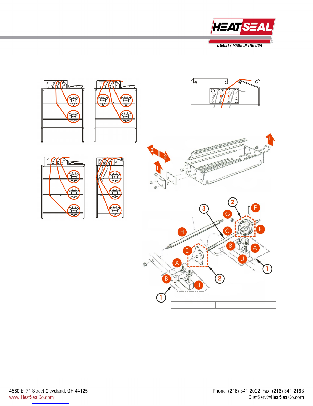
FILM THREADING & MOUNTING
THREADING THE FILM:
Thread the film as shown, one at a time or as needed. FILM SELECTOR
Pull different sized films into film selector and drape unused film
in front of roller.
TO CHANGE FILM WIDTHS:
1. Lift up both handles
2. Move evenly forward or backward
3. Lower into slots
MODEL 102A MODEL 107A
MODEL 104A MODEL 112A
MOUNTING FILM ON AXLE
1. Loosen four wing nuts (A)
2. Swing out upper bearing blocks (B) on both sides
3. Lift out axle assembly (C) and unscrew movable
end cap (D), position fixed end cap (E) for correct
film width then secure with pin (F) and o-ring (G)
4. Position the cardboard core of the film roll against
the taper of the fixed end cap. Make sure the film is
threaded from the bottom of the roll and under film
roller (H) (see threading diagrams)
5. Replace adjustable end cap (D) and screw on tight-
ly
6. Replace the axle assembly (C) and film roll onto
the lower bearing blocks (J), swing upper bearing
blocks (B) back into place and tighten and adjust
wing nuts (A) for desired film tension
ITEM PART # DESCRIPTION
1 6305-018
Bearing Block Set, Includes:
Upper Bearing Block, RH
Upper Bearing Block, LH
Lower Bearing Blocks
2 6110-023
3” Core Adapter Set Includes:
3” Adjustable Core
3” Fixed Core
3 3005-004
3005-047
Core Axle, 21 15/16” L
Core Axle, 24” L
4
Revised 2014
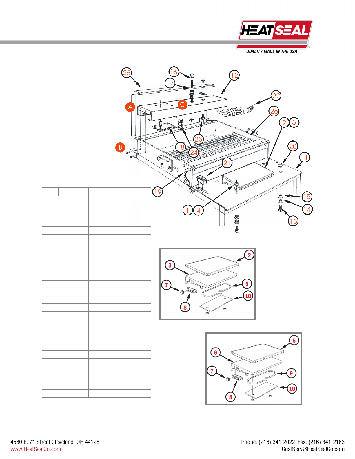
MODEL 102/104/107A REPLACEMENT PARTS
ITEM PART # DESCRIPTION
1 6101-020 6” x 15” Hot Plate Assembly
2 5901-011 6” x 15” Non-stick Cover
3 6305-076 6” x 15” Hot Plate
4 6102-043 8” x 15” Hot Plate Assembly
5 5901-001 8” x 15” Non-stick Cover
6 6305-079 8” x 15” Hot Plate
7 2145-005 Thermostat Knob
8 1881-002 Thermostat
9 6110-016 Element Assembly
10 6305-080 Retainer Plate
11 6102-063 Front Plate
12 6102-031 Control Housing
13 1903-188 #10-32 Screw
14 1907-005 #10 Lock Washer
15 1909-026 #10 Flat Washer
16 1821-034 1 Amp Fuse, Slo-Blo
17 1821-013 Fuse Holder
18 1818-001 Control Board
19 1824-011 Hot Rod 23” L
20 1833-002 Insulator Washer
21 1836-002 Pilot Light
22 1851-052 Power Cord
23 1872-008 Toggle Switch
24 1875-002 Terminal Block
25 6102-052 Wrapping Bridge
26 6102-050 Film Selector Assy.
6” X 15” HOT PLATE FOR MODEL 102
8” X 15” HOT PLATE FOR MODELS 104,107
TO REMOVE ELECTRICAL BOX:
Lift up wrapping bridge (A)
Remove screws (B) from both
sides of electrical control hous-
ing (C)
Lift out electrical control housing
5
Revised 2014
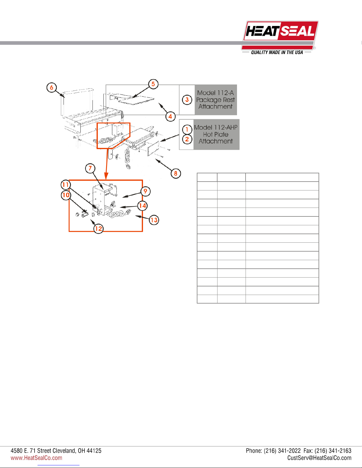
MODEL 112A/112AHP REPLACEMENT PARTS
ITEM PART # DESCRIPTION
1 6107-020 Hot Plate Assembly Kit
2 6101-020 6” x 15” Hot Plate Assembly
3 6106-017 Package Rest Assy.
4 6106-085 Mounting Bracket
5 6106-086 Package Rest
6 6106-031 Wrapping Bridge
7 6106-081 Control Housing
8 6106-089 Control Housing Cover
9 1818-001 Control Board
10 1821-034 1 Amp Fuse, Slo-Blo
11 1821-013 Fuse Holder
12 1836-004 Pilot Light
13 1851-052 Power Cord
14 1872-008 Toggle Switch
6
Revised 2014
ELECTRICAL SERVICE INFORMATION
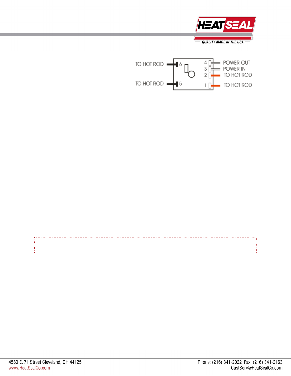
HOT ROD CIRCUIT BOARD TEST
A standard 115 volt neon circuit tester can be used for these tests.
CHECKING FUSES
Remove the fuse from their housing units located on the front of the electrical box. If a visual inspection does not verify a blown
fuse check for continuity by using the meter to read across the two terminals of the fuse.
If the meter reading does not show continuity, replace the fuse.
CHECKING THE HOT ROD
With the power turned OFF, remove the red hot rod wires from Terminals 1 and 2. Using the meter, measure the resistance of
the rod by connecting the leads of the meter to the red wires.
The meter should read between 130-136 ohms. If the reading is out of this range, replace the hot rod.
CHECKING THE CIRCUIT BOARD
After the hot rod and both the fuses have passed the above testing procedures, the circuit board can be tested.
With all the wires shown in the example circuit board (above) properly connected and the power ON, use the meter to test the
voltage across Terminals 1 and 2. If there is no voltage being read, the board needs to be replaced.
ELECTRICAL REQUIREMENTS
All Models are 110 Volts, 10 Amps.
THIS UNIT SHOULD NOT BE OPERATED IF ROD TEMPERATURE EXCEEDS
300 DEGREES FAHRENHEIT. IF SMOKE OR FUMES ARE DETECTED, DISCONTINUE USE
7
Revised 2014
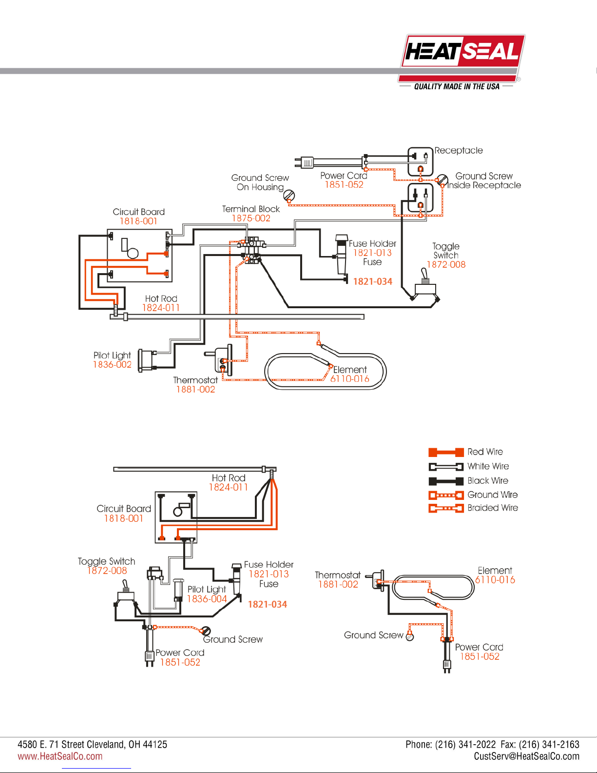
ELECTRICAL DIAGRAMS
FOR MODELS 102A, 104A, 107A
FOR MODEL 112A
FOR MODEL 112AHP

8
Revised 2014
ELECTRICAL BOX & HOT PLATE PARTS
HOT PLATE REPLACEMENT PARTS
ITEM PART # DESCRIPTION
1 6305-076 Hot Plate, 6 by 15
6305-079 Hot Plate, 8 by 15
2 6110-016 Element
3 6305-080 Element Support Plate
4 1881-002 B-200 Thermostat
5 2145-023 Knob
ELECTRICAL BOX REPLACEMENT PARTS
ITEM PART # DESCRIPTION
1 1818-001 Circuit Board
2 1821-013 Fuse Holder
3 1821-002 Fuse, 1 Amp AGC
4 1875-002 Terminal Block
5 1836-004 Pilot Light, Red
6 1872-008 Toggle Switch
7 1851-052 Power Cord, 5 Ft.
8 1869-003 Strain Relief
TO SERVICE ELECTRICAL PARTS ON ELECTRICAL BOX:
Lift up the wrapping bridge, then remove the screws holding the
electrical control housing to the base. Lift out and replace parts.
TO SERVICE ELECTRICAL PARTS ON HOT PLATE:
Remove from wrapper base and replace worn or defective parts.
This manual suits for next models
4
Table of contents
Other Heat Seal Industrial Equipment manuals


