Guralp Systems CMG-3TB Manual

CMG-3TB
Operator’s guide
Part MAN-BHO-0001
Designed and manufactured by
Güralp ystems Limited
3 Midas House, Calleva Park
Aldermaston RG7 8EA
England
Proprietary Notice: The information in this manual is
proprietary to Güralp ystems Limited and may not be
copied or distributed outside the approved recipient's
organisation without the approval of Güralp ystems
Limited. Güralp ystems Limited shall not be liable for
technical or editorial errors or omissions made herein,
nor for incidental or consequential damages resulting
from the furnishing, performance, or usage of this
material.
Issue C 2006-11-15

CMG-3TB
Table of Contents
1 Introduction............................................................................................................... 4
1.1 ystem configuration.......................................................................................... 5
1.2 Digital borehole installations............................................................................. 6
1.3 The hole lock system.......................................................................................... 7
The single-jaw hole lock...................................................................................... 7
The three-jaw hole lock........................................................................................ 9
2 Assembling the instrument.................................................................................... 11
2.1 Unpacking and packing.................................................................................... 11
2.2 Handling notes.................................................................................................. 11
2.3 Assembling the 3TB.......................................................................................... 12
2.4 Disassembling the instrument.......................................................................... 16
2.5 Control units..................................................................................................... 17
The breakout box................................................................................................ 17
Calibration...................................................................................................... 18
Mass locking and unlocking.......................................................................... 19
Centring.......................................................................................................... 19
The handheld control unit................................................................................. 19
Connections.................................................................................................... 20
ignal meter................................................................................................... 20
Calibration and control.................................................................................. 21
Banana plugs.................................................................................................. 21
The inclinometer monitor unit.......................................................................... 21
2.6 Operating the hole lock.................................................................................... 22
Engaging the hole lock....................................................................................... 23
Disengaging the hole lock.................................................................................. 24
Manual operation............................................................................................... 24
3 Installing the 3TB in a borehole............................................................................. 26
3.1 Installing a sensor with hole lock unit............................................................. 26
3.2 Installing a sensor using sand backfill............................................................. 31
Procedure............................................................................................................ 32
3.3 Assembling the winch...................................................................................... 36
3.4 Earthing a borehole sensor............................................................................... 40
Installations with AC power supplies............................................................... 40
Installations with DC power supplies................................................................ 44
External lightning protection............................................................................. 45
3.5 Levelling and centring...................................................................................... 46
3.6 Downhole orientation....................................................................................... 47
2 Issue C

Operator's guide
Installing the cream! extension....................................................................... 47
Installing the reference instrument................................................................... 47
Measuring the orientation.................................................................................. 48
Applying automatic rotation.............................................................................. 53
4 Calibrating the 3TB................................................................................................. 55
4.1 The calibration pack......................................................................................... 55
Poles and zeroes................................................................................................. 56
Frequency response curves................................................................................ 57
Obtaining copies of the calibration pack........................................................... 57
4.2 Calibration methods......................................................................................... 58
4.3 Calibration with cream! ................................................................................ 58
ensor response codes........................................................................................ 62
4.4 Calibration with a handheld control unit........................................................ 62
4.5 The coil constant.............................................................................................. 63
5 Inside the 3TB......................................................................................................... 64
5.1 The sensors....................................................................................................... 64
5.2 The control system........................................................................................... 66
LOCK .................................................................................................................. 66
UNLOCK ............................................................................................................ 67
CENTRE ............................................................................................................. 69
5.3 The feedback system........................................................................................ 70
Hybrid feedback................................................................................................. 71
Conventional-response feedback....................................................................... 72
Comparisons....................................................................................................... 72
6 Connector pinouts................................................................................................... 74
7 pecifications.......................................................................................................... 76
8 Revision history...................................................................................................... 78
November 2006 3
CMG-3TB
1 Introduction
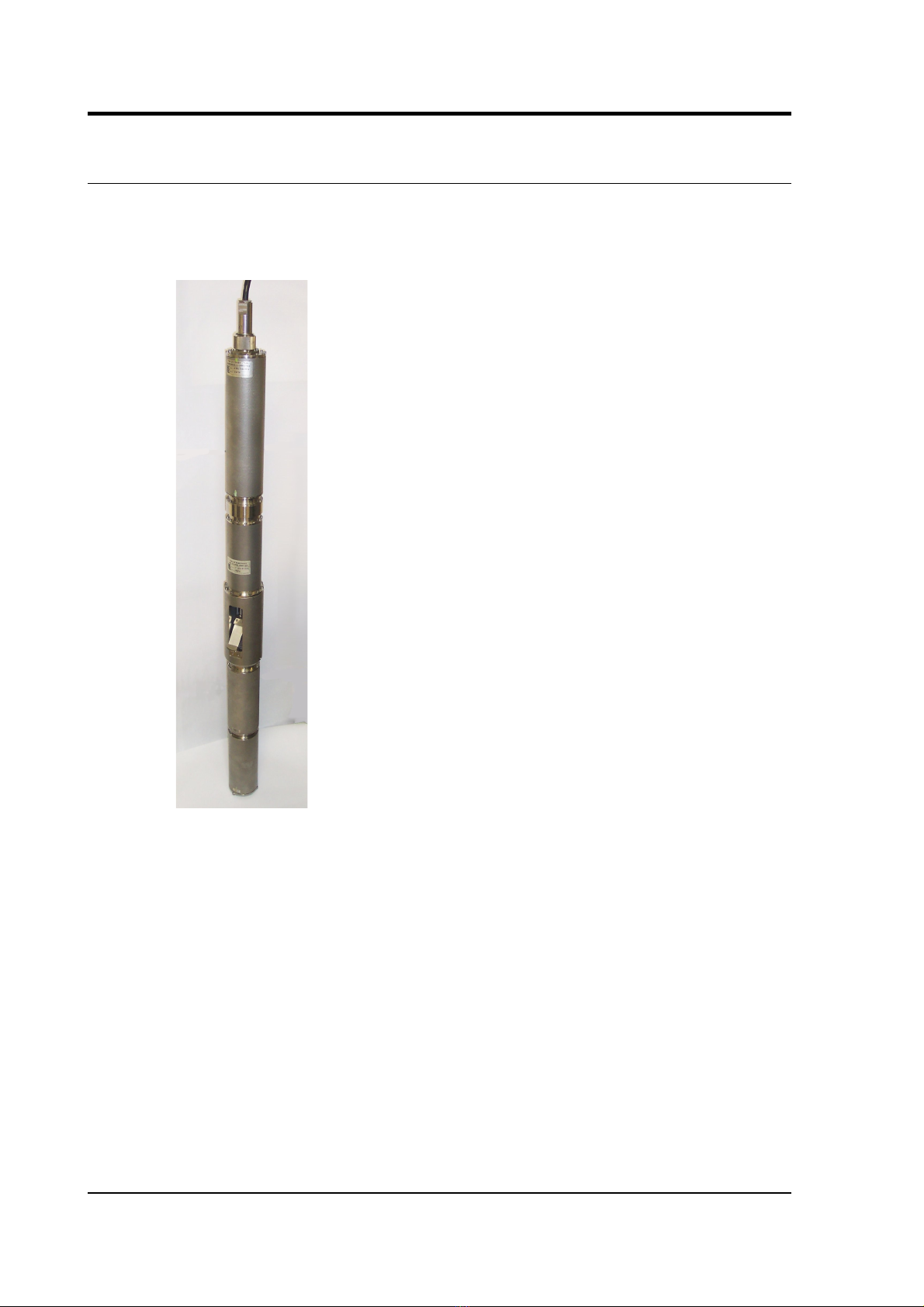
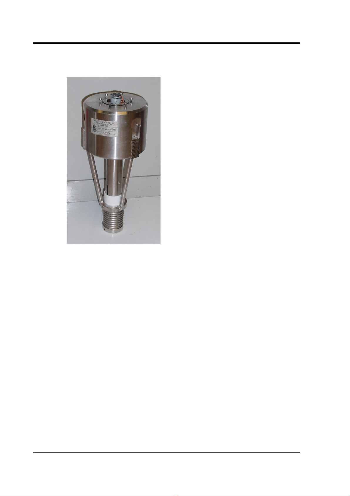
The CMG-3TB is a three-axis seismometer consisting of three sensors
stacked vertically in a sealed borehole sonde, designed for use in cased
boreholes with diameters between 5” / 89 mm and 9” / 229 mm.
The seismometer system is self-contained except for its 12 – 30 V
power supply, which is provided through the same cable as the
analogue data. ensor functions such as levelling and mass locking are
carried out through a surface control box.
The 3TB's sensors are sensitive to ground vibrations in the frequency
range 0.0027 – 50 Hz. It outputs analogue voltage representing ground
velocity on balanced differential lines. Each seismometer is delivered
with a detailed calibration sheet showing its serial number, measured
frequency response in both long and short period sections of the
seismic spectrum, sensor DC calibration levels, and the transfer
function in poles/zeros notation.
4 Issue C
Operator's guide
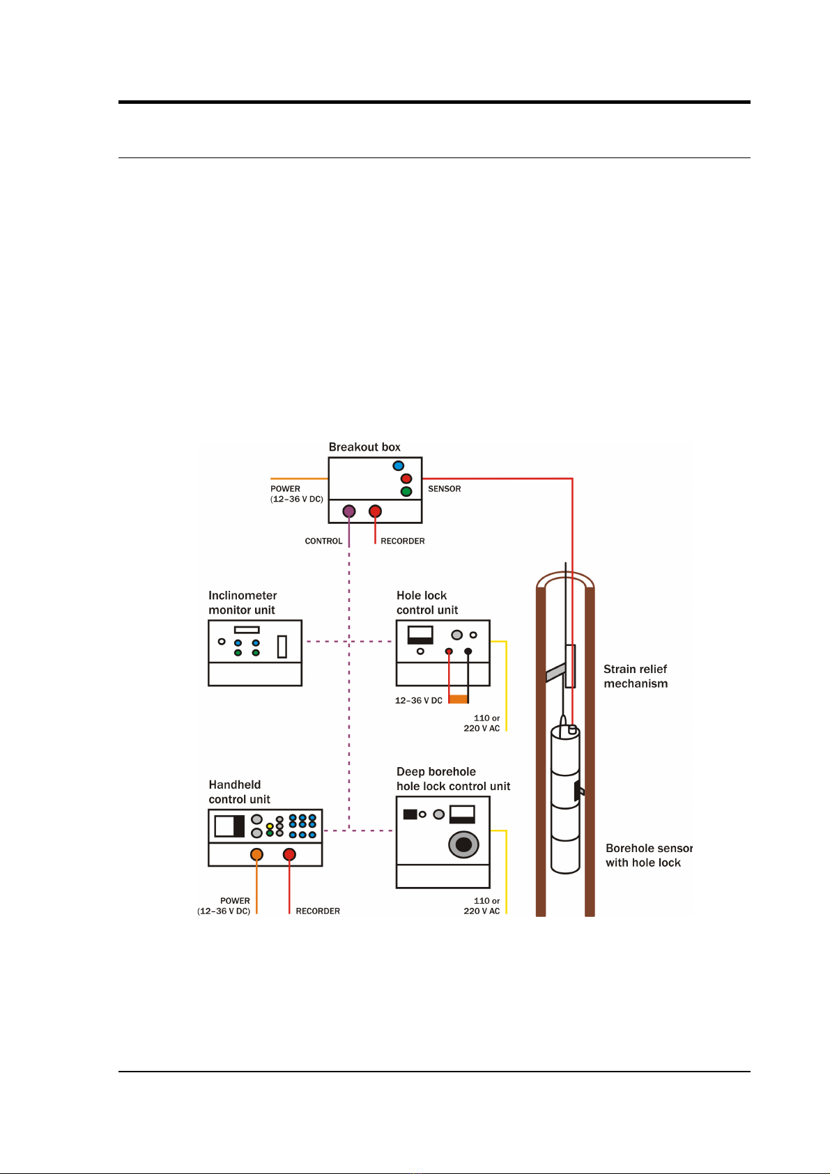
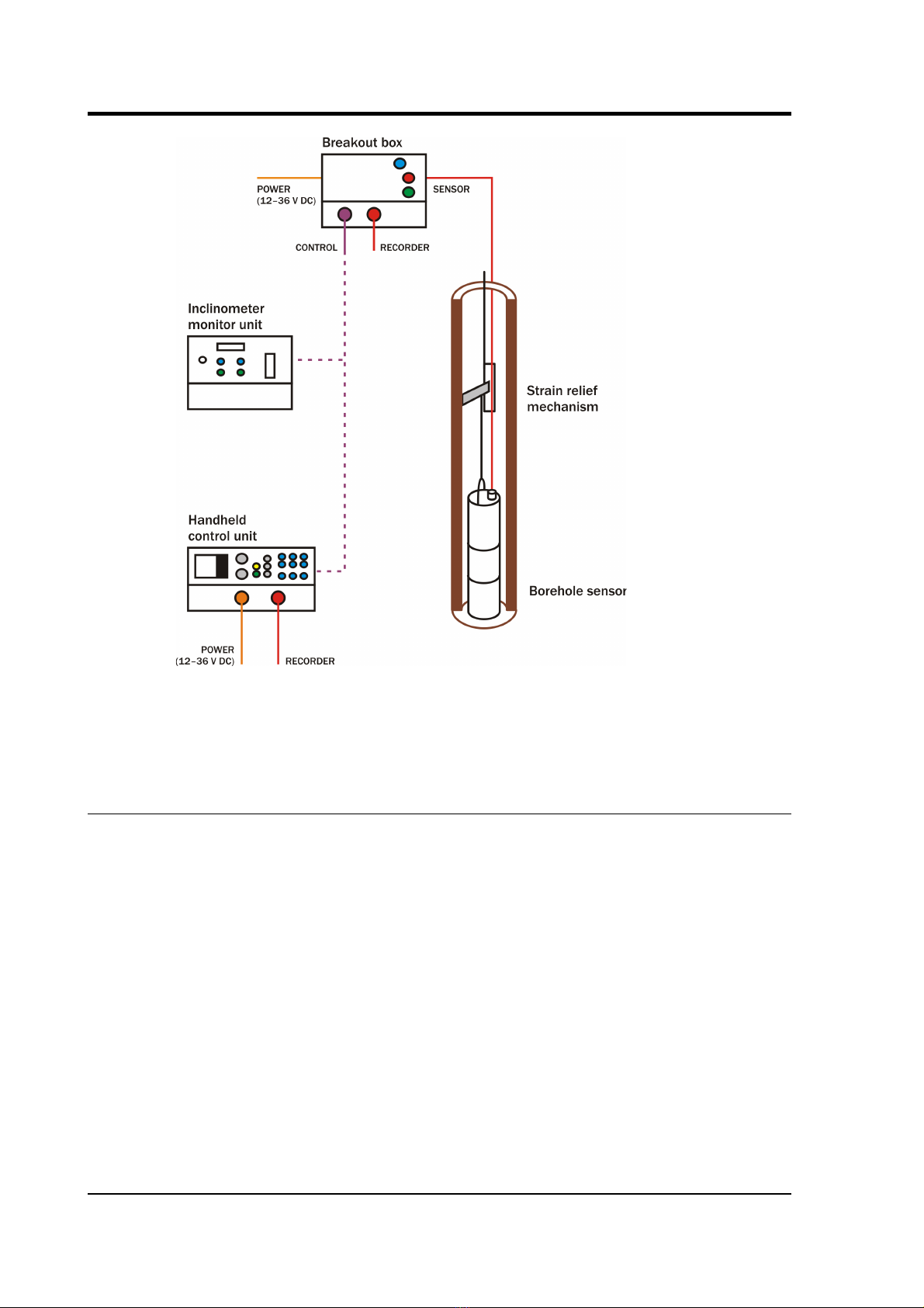
1.1 Syste configuration
The CMG-3 series of seismic instruments share a number of features:
•a modular sensor sonde, which can be fitted with a single-jaw or
three-jaw holelock mechanism as required,
•a pit head installation including a breakout box, and
•a number of additional, optional control units which may be
connected to the breakout box to perform installation and
maintenance tasks.
For example, a borehole or pit installation of a CMG-3TB or 3E PB
instrument with single-jaw hole lock has the following layout:
CMG 3-series instruments are also suitable for installing in boreholes
with sand backfill. In this case no hole lock unit is necessary.
November 2006 5
CMG-3TB
The CMG-3V sensor is identical to the vertical-component module of
the 3TB instrument, allowing you to build mixed arrays of 3V and 3TB
sensors with identical response characteristics.
1.2 Digital borehole installations
The Güralp DM24 digitizer is available in a borehole sonde form.
Connecting a Güralp borehole instrument to a downhole digitizer
allows you to construct a true digital borehole installation. This has
several advantages over a traditional borehole setup:
•Digital signals are not subject to attenuation as they travel up to
the surface, so signals received are stronger and more reliable.
•Digitizing the data at source allows you to ensure that its origin
can be reliably traced.
•The DM24 digitizer may also be combined with an
Authentication Module within the borehole sonde, allowing you
to generate cryptographically-signed data at the point of origin.
6 Issue C

Operator's guide
A digital borehole installation can be provided with R 232, R 422 or
fibre-optic links to the surface, depending on the depth of the
borehole.
When a downhole digitizer is present, it takes the place of the strain
relief unit in the borehole. The surface unit also takes a slightly
different form, with a serial connector allowing you to attach a modem
or other communications link. In this type of installation, instead of
using the surface unit to pass control signals to the sensor, all
functions can be accessed remotely
via
the digitizer.
If you prefer to install a stand-alone digitizer at the surface, it should
be connected to the 19-pin
RECORDER
socket of the breakout box.
1.3 The hole lock syste
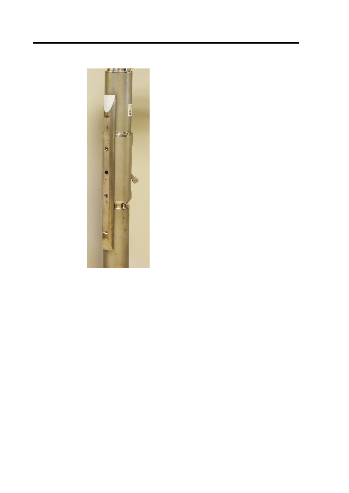
The hole lock clamp unit in a 3TB instrument provides a stable
platform for the sensor modules mounted above and below it. It is
designed to maintain a positive pressure on the borehole casing over a
prolonged period of time without attention, and to fix the sonde in
place whilst avoiding transmitting any stresses.
Güralp ystems hole locks are constructed to order from accurate
measurements of your borehole at the depth you wish to install the
instrument. Either single-jaw or three-jaw hole lock units can be
manufactured.
In installations with sand backfill, or where the instrument rests on the
bottom of the borehole, a hole lock may be unnecessary.
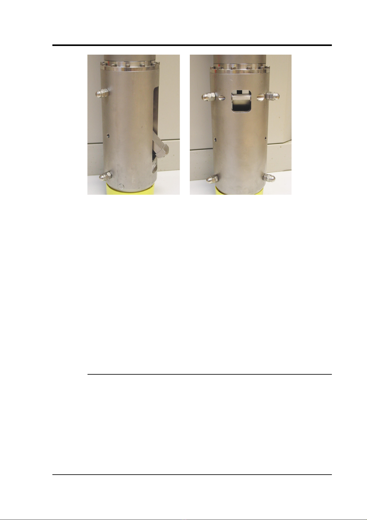
The single-jaw hole lock
The single jaw hole lock is the standard option for triaxial borehole
instruments. It consists of an active clamp arm and a number of skids
or studs on the sonde body. The arm is attached to a compression
spring, which forces it to swing out from the sonde and wedge the
body against the borehole wall. A serrated steel jaw at the end of the
arm provides maximum grip against the borehole casing. The skids or
studs and the locking arm together form a multi-point clamp, which
aligns the sonde body parallel to the axis of the borehole and holds it
firmly in place so that it cannot twist or slip under the influence of
ground vibrations.
There are several configurations of skids and studs which can provide
a suitable clamp. Either
•the locking jaw pushes two steel skids against the side of the
November 2006 7
CMG-3TB
borehole, providing two line contacts;
•only the tips of the skids come into contact with the borehole,
providing three point contacts;
•a single skid is combined with a pad to provide one line and one
point contact; or
•three studs provide three point contacts.
8 Issue C
Operator's guide
tuds have the advantage of being smaller than skids, but the contact
points are very close to each other. You should evaluate the various
locking methods available to see which works best in your borehole.
The spring inside the lock provides around 60 kg of force at its locking
position. A DC actuator retracts the arm into the body of the lock so
that the sensor mechanism can be installed and removed. The actuator
consists of a 14 W DC motor with a planetary reduction gearhead,
which drives the nut of a ball lead screw through the helical drive
gears. The thread of the lead screw is prevented from turning, and so
moves linearly when the nut turns.
The motor has a power system separate from that of the sensor, and
can be controlled from the surface using a hole lock control unit. Once
the sonde is installed, the hole lock control unit may be removed.
Without power, the hole lock will not be able to retract, and the sensor
will be secured.
The three-jaw hole lock
A three-jaw hole lock is available which gives better grip on the
borehole casing, but is bulkier and heavier than the single-arm lock.
This is the standard option for uniaxial instruments; it can be installed
in boreholes between 3.5” / 89 mm and 7” / 178 mm in diameter.
The three-jaw hole lock consists of a set of three active clamp arms
attached to a compression spring, which forces them to swing out from
the sonde and wedge themselves against the borehole wall. errated
steel jaws at the end of each arm provides maximum grip against the
borehole casing. This configuration ensures that the sonde body is
November 2006 9
CMG-3TB
held parallel to the axis of the borehole and prevented from twisting or
slipping under the influence of ground vibrations.
10 Issue C
Table of contents
Other Guralp Systems Measuring Instrument manuals


