Fröling T4e User manual

Operating Instructions
Flue gas pipe connection
T4e 20-250 / PT4e 120-250
Translation of the original German operating instructions for the operator
Read and follow the instructions and safety information!
Technical changes, typographical errors and omissions reserved!
M2180221_en | Edition 28/05/2021
Fröling GesmbH | A-4710 Grieskirchen, Industriestraße 12 | www.froeling.com
1 General
The flue gas pipe connection for the T4e wood chip boiler can be rebuilt from the top
to the rear. The following steps illustrate the work on a T4e with stoker on the left side
of the boiler. Work on a T4e with stoker on the right side of the boiler can be carried
out in the same way but on the opposite side.
❒Switch off the boiler and allow it to cool down
❒ Switch off the power supply to the boiler
CAUTION
Assembly and installation by unqualified persons:
Risk of personal injury and damage to property
During assembly and installation:
❒ Observe the instructions and information in the manuals
❒ Only allow appropriately qualified personnel to work on the system
❒In addition to these instructions, please also note the warnings in the operating
and installation manual for the boiler.
1General
2 Fröling GesmbH | A-4710 Grieskirchen, Industriestraße 12 | www.froeling.com
2 T4e 20-60
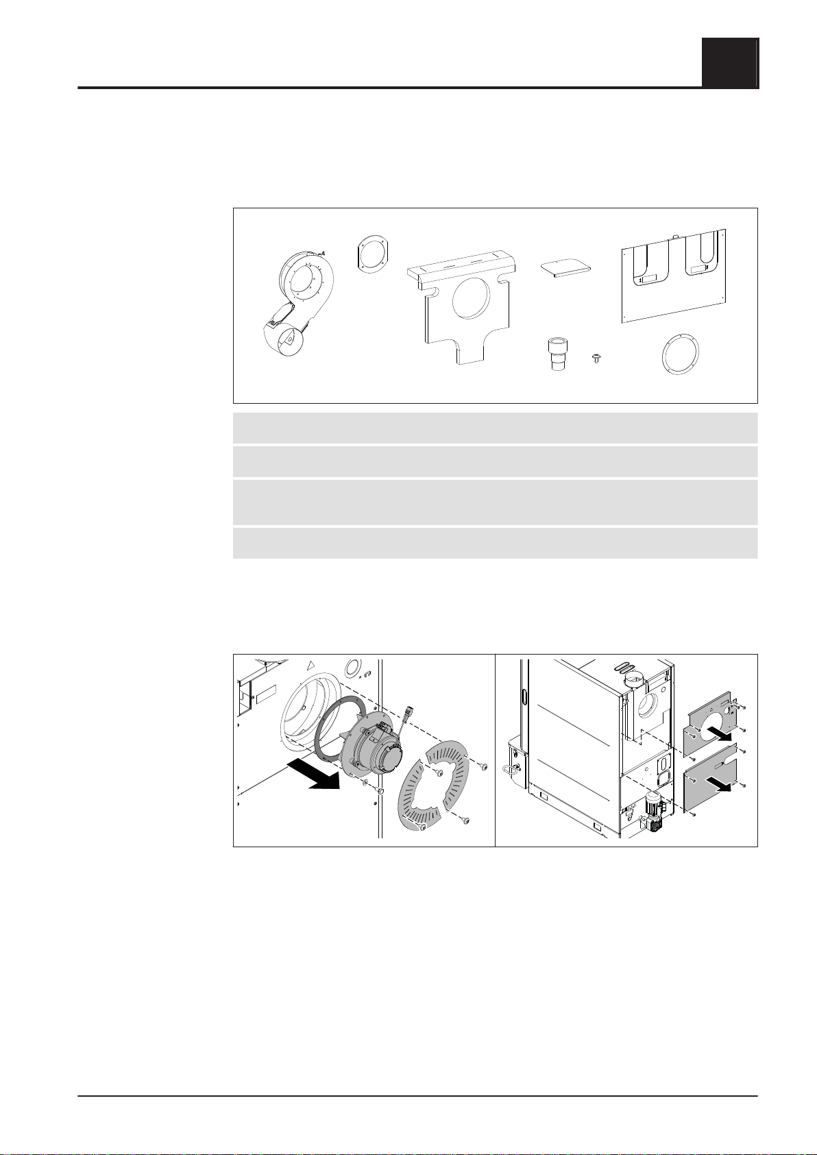
2.1 Materials supplied
1
2
34
5
6
7
8
1Induced draught unit housing 5Adapter for Lambda probe
2Seal for induced draught housing 6Assembly material
3Thermal insulation for induced
draught unit housing
7Centre back panel
4Cover plate for insulating cover 8Seal for induced draught fan
Not pictured: Documentation
2.2 Assembly
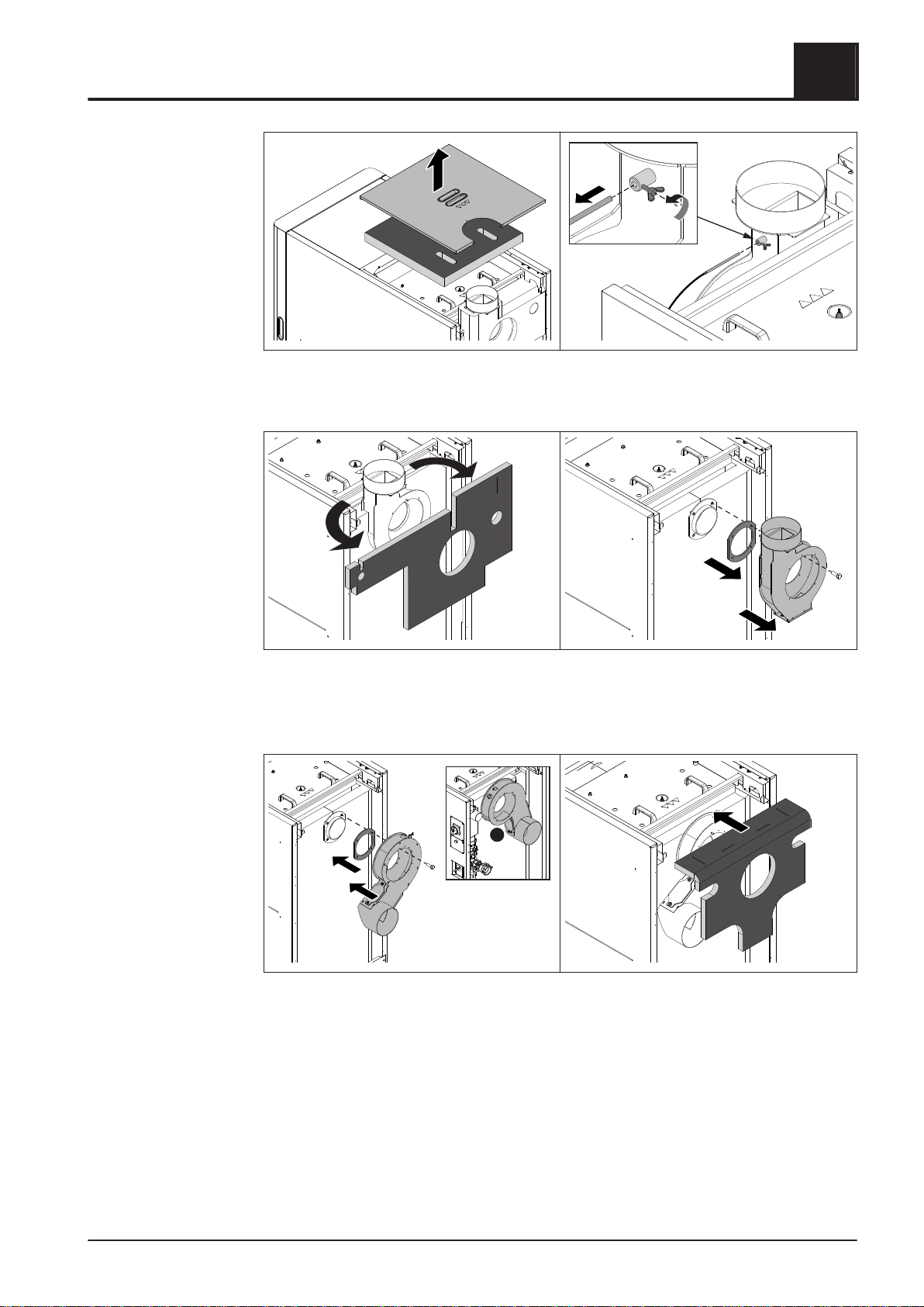
❒ Remove the cover plates for the ID fan from the back of the boiler
❒ Unplug the induced draught fan cable and remove the induced draught fan
❒ Remove upper and centre back panel
➥Centre back panel is no longer required
T4e 20-60 2
Materials supplied
Operating Instructions Flue gas pipe connection | M2180221_en 3

❒ Take off the insulating cover and thermal insulation above the heat exchanger
❒Unscrew the Lambda probe from the induced draught housing
❒ Loosen the wing screw and remove the flue gas temperature sensor
❒ Remove the thermal insulation from the induced draught housing
❒Remove the induced draught housing and seal
➥Thermal insulation, induced draught housing and seal are no longer required
❒ Install the enclosed induced draught housing and seal on the flue gas flange
➥Position the flue gas pipe connection on the side averted to the stoker!
➥A: Version: Stoker right
❒ Place thermal insulation on induced draught housing
2T4e 20-60
Assembly
4 Fröling GesmbH | A-4710 Grieskirchen, Industriestraße 12 | www.froeling.com
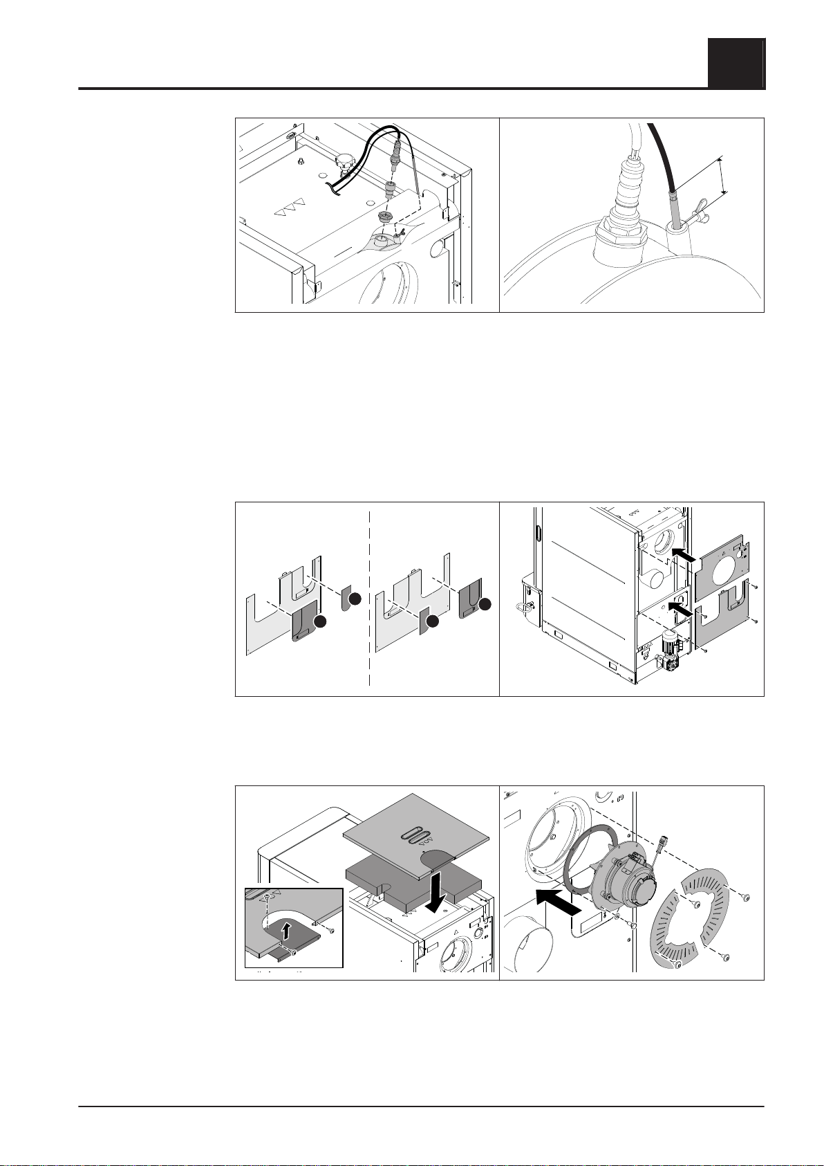
20mm
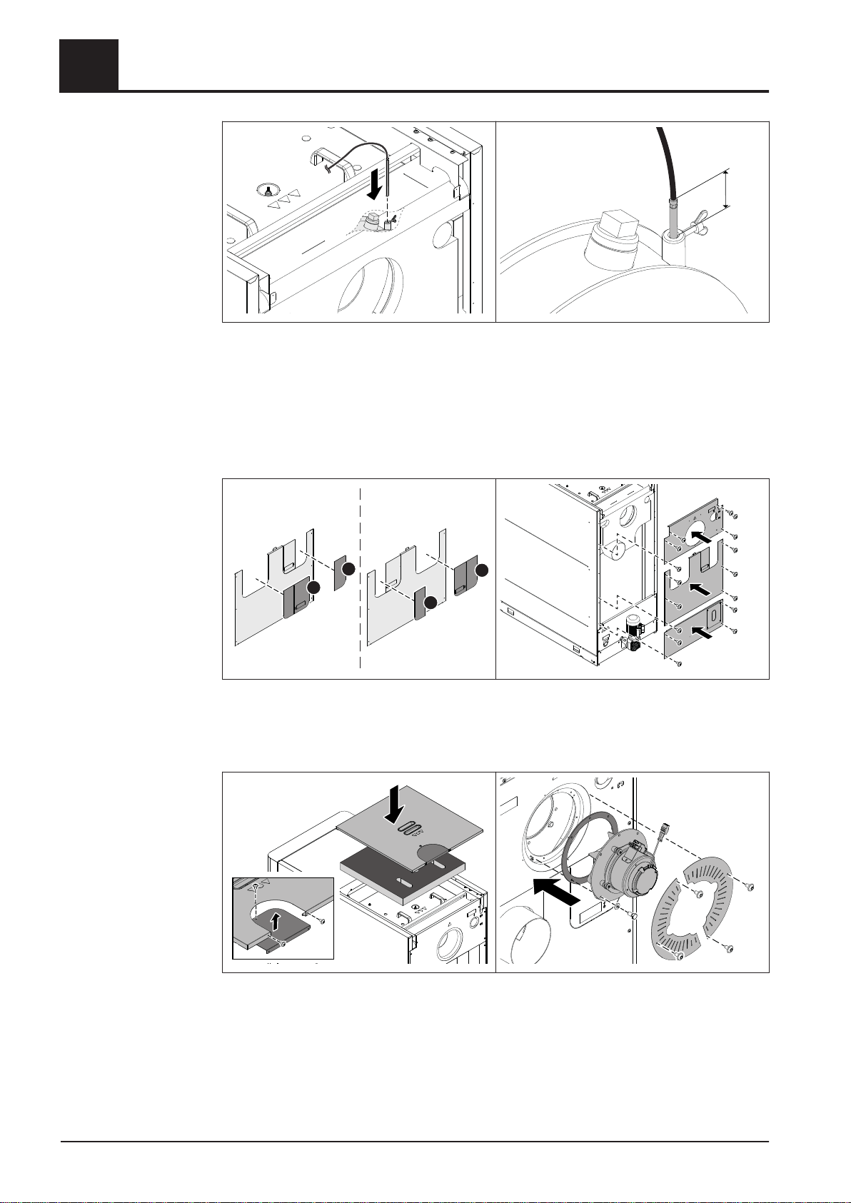
❒ Screw plastic bushing, adapter and Lambda probe into the induced draught
housing
❒Push the flue gas temperature sensor into the sleeve on the induced draught
housing so that it protrudes approx. 20 mm from the sleeve and secure the
position with a wing screw
NOTICE! If flue gas recirculation is intended on the boiler, the following assembly
steps can be interrupted and continued after installation of the flue gas recirculation.
A
A
B
B
Stoker left: Stoke right:
❒ Punch out perforations for the flue gas pipe (A) and return connection (B) on the
supplied back panel shown, depending on the stoker side
❒Install the back panels on the boiler
❒ Secure the cover plate from the inside on the cut-out in the rear cover
❒ Fit thermal insulation and insulating cover on the heat exchanger
❒ Install the induced draught fan and the supplied seal
❒ Plug in the cable for the induced draught fan again
❒ Install the cover plates for the ID fan on the back of the boiler
T4e 20-60 2
Assembly
Operating Instructions Flue gas pipe connection | M2180221_en 5
3 T4e 80-110 / PT4e 120
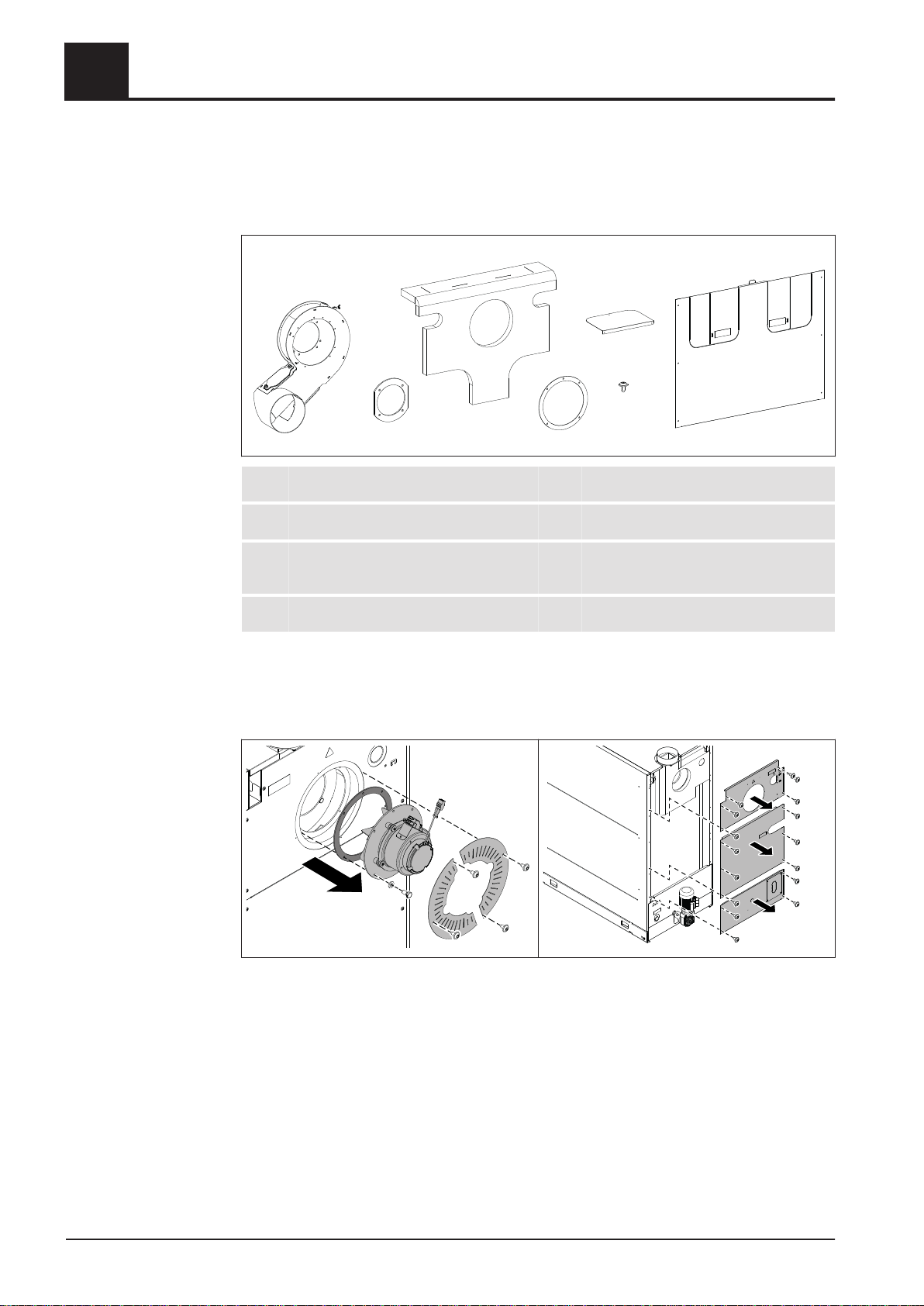
3.1 Materials supplied
1
2
3
4
6
5
7
1Induced draught unit housing 5Seal for induced draught fan
2Seal for induced draught housing 6Assembly material
3Thermal insulation for induced
draught unit housing
7Centre back panel
4Cover plate for insulating cover
Not pictured: Documentation
3.2 Assembly
❒ Remove the cover plates for the ID fan from the back of the boiler
❒ Unplug the induced draught fan cable and remove the induced draught fan
❒ Remove the back panels
➥Centre back panel is no longer required
3T4e 80-110 / PT4e 120
Materials supplied
6 Fröling GesmbH | A-4710 Grieskirchen, Industriestraße 12 | www.froeling.com
❒ Take off the insulating cover and thermal insulation above the heat exchanger
❒Loosen the wing screw and remove the flue gas temperature sensor
❒ Remove the thermal insulation from the induced draught housing
❒Remove the induced draught housing and seal
➥Thermal insulation, induced draught housing and seal are no longer required
A
❒ Install the enclosed induced draught housing and seal on the flue gas flange
➥Position the flue gas pipe connection on the side averted to the stoker!
➥A: Version: Stoker right
❒ Place thermal insulation on induced draught housing
T4e 80-110 / PT4e 120 3
Assembly
Operating Instructions Flue gas pipe connection | M2180221_en 7
20mm
❒ Push the flue gas temperature sensor into the sleeve on the induced draught
housing so that it protrudes approx. 20 mm from the sleeve and secure the
position with a wing screw
NOTICE! If flue gas recirculation is intended on the boiler, the following assembly
steps can be interrupted and continued after installation of the flue gas recirculation.
Stoker left: Stoke right:
A
B
A
B
❒ Punch out perforations for the flue gas pipe (A) and return connection (B) on the
supplied back panel shown, depending on the stoker side
❒Install the back panels on the boiler
❒ Secure the cover plate from the inside on the cut-out in the rear cover
❒Fit thermal insulation and insulating cover on the heat exchanger
❒ Install the induced draught fan including seal
❒ Plug in the cable for the induced draught fan again
❒ Install the cover plates for the ID fan on the back of the boiler
3T4e 80-110 / PT4e 120
Assembly
8 Fröling GesmbH | A-4710 Grieskirchen, Industriestraße 12 | www.froeling.com
4 T4e 130-180 / PT4e 140-180
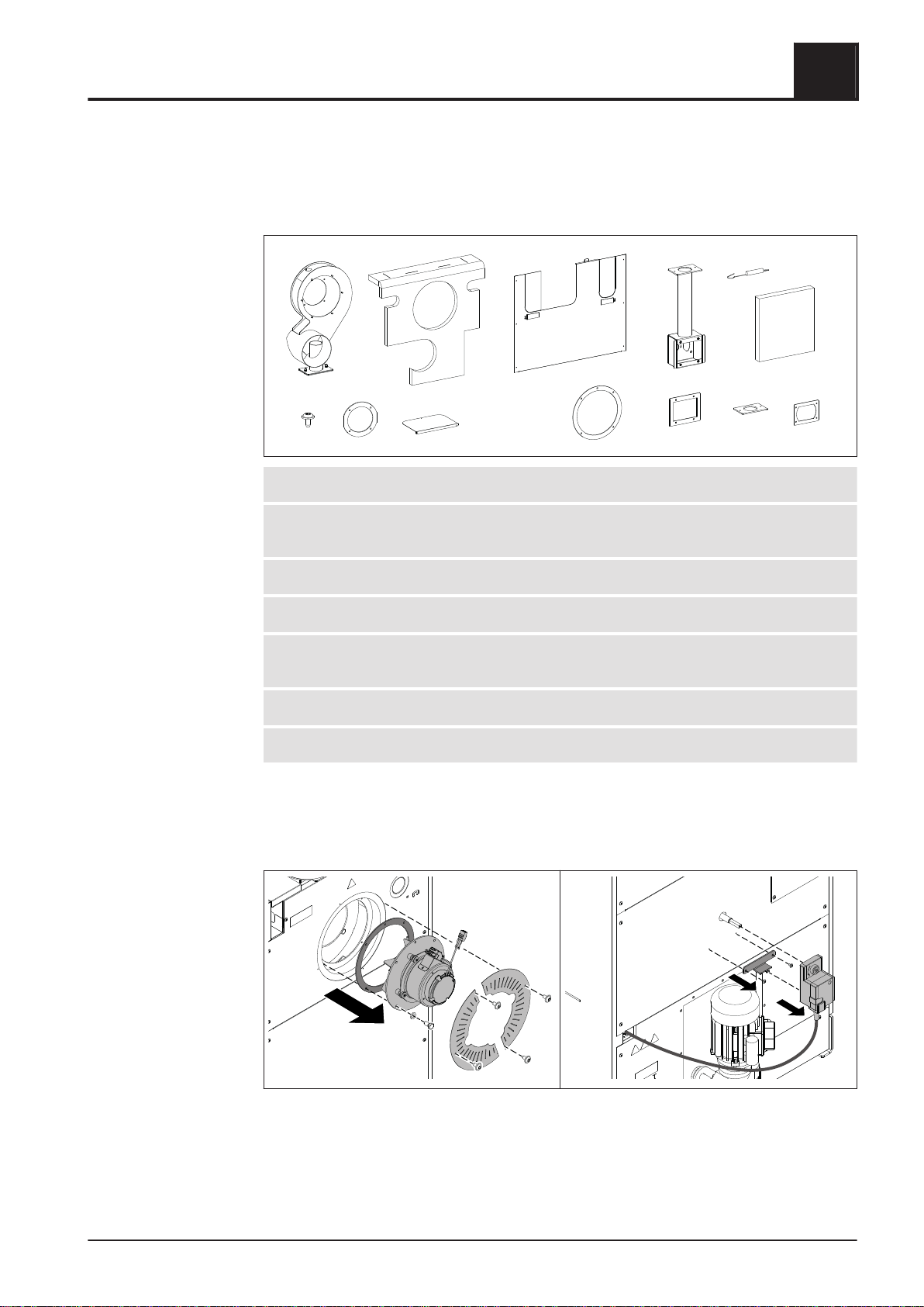
4.1 Materials supplied
12
4
35
689
10
11 12 13
7
1Induced draught unit housing 8Flue gas recirculation duct
2Thermal insulation for induced
draught unit housing
9Tension spring
3Assembly material 10 Thermal insulation duct
4Seal for induced draught housing 11 Seal for servo-motor cover
5Cover plate for insulating cover 12 Seal for flue gas recirculation induced
draught housing
6Centre back panel 13 Seal for flue gas recirculation boiler
7Seal for induced draught fan
Not pictured: Documentation
4.2 Assembly
❒ Remove the cover plates for the ID fan from the back of the boiler
❒Unplug the induced draught fan cable and remove the induced draught fan
❒ Loosen the screws on the torque support and pull the servo-motor off the shaft
➥Position the servo-motor up against the installation so that the servo-motor is
not damaged!
T4e 130-180 / PT4e 140-180 4
Materials supplied
Operating Instructions Flue gas pipe connection | M2180221_en 9

❒ Remove the back panels
➥Centre back panel is no longer required
❒Take off both insulating covers and thermal insulation above the heat exchanger
❒ Loosen wing screw and pull out flue gas temperature sensor on the induced
draught housing
❒Remove the thermal insulation from the induced draught housing
➥Thermal insulation is no longer required
❒ Unhook the tension springs and remove the thermal insulation
❒ Loosen the cover on the flue gas recirculation duct and remove the air damper
4T4e 130-180 / PT4e 140-180
Assembly
10 Fröling GesmbH | A-4710 Grieskirchen, Industriestraße 12 | www.froeling.com
Other manuals for T4e
1
This manual suits for next models
1
Table of contents
Other Fröling Industrial Equipment manuals

Fröling
Fröling FBR-G User manual

Fröling
Fröling FBR-G2 User manual

Fröling
Fröling BFSU User manual

Fröling
Fröling GAR 110 User manual

Fröling
Fröling BFSV-H User manual

Fröling
Fröling Turbomat 320 User manual

Fröling
Fröling TGR 110 User manual

Fröling
Fröling Screening screw 150 User manual

Fröling
Fröling 250 User manual

Fröling
Fröling BFSV User manual


