FLS FLOWX3 F9.63 User manual

F9.63 Electromagnetic insertion flow sensor
1
F9.63 Flow Monitor and Transmitter
INSTRUCTION MANUAL
EN 10-11
Table of Contents
1. Introduction…………………………………………………………………. 3
1.1. Safety Instructions………………………………………………………………. 3
1.2. Unpacking…………………………………………………………………………. 3
2. Description………………………………………………………………….. 4
2.1. Design……………………………………………………………………………... 4
2.2. Technical Features……………………………………………………………… 4
2.3. Connection to FlowX3 Sensors………………………………………………. 5
3. Specifications………………………………………………………………. 5
3.1. Technical Data…………………………………………………………………… 5
3.2. Dimensions………………………………………………………………………. 6
4. Installation………………………………………………………………….. 7
4.1. Location…………..……………………………………………………………….. 7
4.2. Wiring……………………………………………………………………………... 8
5. Operational Overview…………………………………………………….. 11
5.1. Keypad Functions………………………………………………………………. 11
5.2. General Operation Flowchart…………………………………………………. 11
6. View Level…………………………………………………………………... 13
7. Menu Directory Level……………………………………………………… 14
7.1. Free access (no password required)………………………………………… 14
7.2. Password protected access…………………………………………………… 14

F9.63 Electromagnetic insertion flow sensor
2
8. Menu and Edit Level………………………………………………………. 15
8.1. Calibration Menu…………………………………………………………………… 15
8.1.1. Unit………………………………………………………………………………. 15
8.1.2. K-Factor…………………………………………………………………………. 16
8.1.3. Size…………………………………………………………………………………16
8.2. Output Menu………………………………………………………………………… 17
8.2.1. 4 – 20mA Output……………………………………………………………….. 17
8.2.2. O.C. Output (OPT)……………………………………………………………… 18
8.2.2.1. O.C. Output (OPT): MIN mode…………..…………………………….… 18
8.2.2.2. O.C. Output (OPT): MAX mode…………..……………………………... 19
8.2.2.3. O.C. Output (OPT): WINDOW mode……..…………………………….. 19
8.2.2.4. O.C. Output (OPT): PULSE mode……….……..……………………….. 20
8.2.3. R1 Output (OUT1)……………………………………………………………… 20
8.2.3.1. R1 Output (OUT1): MIN mode…………………..………………………. 21
8.2.3.2. R1 Output (OUT1): MAX mode…………………..……………………… 21
8.2.3.3. R1 Output (OUT1): WINDOW mode…………..………………………… 22
8.2.3.4. R1 Output (OUT1): PULSE mode……………..………………………… 22
8.3. Simulation Menu……………………………………………………………………. 23
8.3.1. Test 4 – 20mA Loop……………………………………………………………. 23
8.3.2. Test O.C. Output (OPT)……………………………………………………….. 24
8.3.3. Test R1 Output (OUT1)………………………………………………………... 24
8.4. Options Menu……………………………………………………………………….. 25
8.4.1. Contrast…………………………………………………………………………. 25
8.4.2. Filter……………………………………………………………………………… 26
8.4.3. Flow Decimal Point…………………………………………………………….. 26
8.4.4. Total Decimal Point…………………………………………………………….. 27
8.4.5. Loop Adjust 4mA……………………………………………………………….. 27
8.4.6. Loop Adjust 20mA……………………………………………………………… 28
8.4.7. Menu PWD……………………………………………………………………… 28
8.4.8. Restot PWD…………………………………………………………………….. 29
8.4.9. Language……………………………………………………………………….. 29
8.4.10. K-Factor Calculate…………………………………………………………… 30
9. Troubleshooting……………………………………………………………. 31
9.1. Display messages………………………………………………………………….. 31
10.K-Factor Tables…………………………………………………………….. 32
11.Ordering Data………………………………………………………………. 39

F9.63 Electromagnetic insertion flow sensor
3
1. Introduction
1.1. Safety Instructions
General Statements
Do not install and service the instrument without following the Instruction
Manual.
This unit is designed to be connected to other instruments which can be
hazardous if used improperly. Read and follow all associated instrument
manuals before using with this instrument.
Unit installation and wiring connections should only be performed by qualified
staff.
Do not modify product construction.
Installation and Commissioning Statements
Remove power to the instrument before wiring input and output connections.
Do not exceed maximum specifications using the instrument.
To clean the unit, use only chemical compatible products.
1.2. Unpacking
Please verify that the product is complete and without any damage. The following
items must be included:
F9.63 Electromagnetic Flow Sensor
Instruction Manual for F9.63M Flow Sensor

F9.63 Electromagnetic insertion flow sensor
4
2. Description
2.1. Design
The FLOWX3 NEW F9.63M Insertion Magmeter is suitable to measure flowrate in both
metal and thermoplastic pipelines.
No moving mechanical parts and the high quality materials allow the measurement of
liquids where suspended solids can be present or of abrasive liquids as long as they
are conductive and homogeneous.
The sensor can be assembled into the standard FLS fitting range so it is perfectly
interchangeable with the paddlewheel sensors. The new design allows an accurate
flow measurement over a wide dynamic range in pipe sizes from DN15 (0.5”) to
DN600 (24”).
The FLS FlowX3 F9.63 offer an indication and a 4…20 mA signal for long distance
transmission and it also provides one programmable open collector output and two
relay outputs. Self explaining calibration menus allow a customized setup of all
measuring parameters and the state of the art electronic design ensures long-term
reliable and stable signals.
2.2. Technical Features
1) Electronic box
2) PC box
3) External Earth Ground Terminal
4) Cable Gland
5) O-Ring (EPDM or FPM)
6) Sensor body 316L SS or CuNi
7) PVDF or PEEK reading head

F9.63 Electromagnetic insertion flow sensor
5
2.3. Operating Principle
If an electrical conductor is caused to move in a magnetic field, such movement
induces a voltage in the conductor ( Faraday’s law ). The magnetic coil in the body of
the instrument generates a magnetic field perpendicular to the flow direction. The
magnetic field and the velocity induce a voltage between the electrodes. The voltage is
directly proportional to the flow velocity.
The voltage is converted into a flow proportional 4-20 mA output signal or frequency
output signal.
3. Specifications
General
Pipe Size Range: DN15 to DN600 (0.5” to 24”). Please refer to Installation Fitting
section for more details.
Flow Rate Range: 0.15 to 8 m/s (0.15 to 25 ft/s).
Full Scale Range : 5 m/s (16,4 ft/s) standard (others available on request).
Linearity: 1% of reading + 1,0 cm/s
Repeatability: 0.5% of reading
Enclosure: IP65
Materials:
oCase: PC/PVC
oGasket: EPDM
Display:
o3 line LCD: 2 x 12 alphanumeric lines + 1 icon line
oUpdate rate: 1 second
oUser adjustable with 5 levels
Wetted Materials:
oSensor body: 316L SS/PVDF or CuNi/PVDF or 316L SS/PEEK
oO-rings: EPDM or FPM
oElectrodes: 316L SS or CuNi
Electrical
Power Supply:
o12-24 VDC + 10% regulated (reverse polarity and short circuit protected)
oMaximum current consumption: 300 mA
o Protective earth: < 10 Ω
Current output:
o4 – 20 mA, isolated, fully adjustable and reversible
o Max. loop impedance: 600 Ω @ 24 VDC
oFrequency output:
Open Collector output:
oUser selectable as MIN alarm, MAX alarm, Window alarm, Pulse Out, Off
oOptically isolated, 50 mA MAX sink, 24 VDC MAX pull-up voltage
oMax pulse/min: 300
oHysteresis: User selectable
F9.63 Electromagnetic insertion flow sensor
6
Relay output:
oUser selectable as MIN alarm, MAX alarm, Window alarm, Pulse Out, Off
oMechanical SPDT contact
oMax pulse/min: 180
oHysteresis: User selectable
Environmental
Storage Temperature: -10°C to +60°C (14°F to 140°F)
Ambient Temperature: 0°C to +60°C (32°F to 140°F)
Relative Humidity: 0 to 95% (non-condensing)
Fluid conditions:
ohomogeneous liquids, pastes or slurries, also with solid content
o Min Electrical Conductivity: 20 μS
oTemperature: -10°C to 60°C (14°F to 140°F) with PVDF reading head
oTemperature: -10°C to 150°C (14°F to 302°F) with PEEK reading head
Max. operating pressure:
o16 bar @ 25°C (232 psi @ 77°F)
o8.6 bar @ 60°C (124 psi @ 140°F)
Standards & Approvals
Manufactured under ISO 9001 (Quality)
Manufactured under ISO 14001 (Environmental Management)
CE
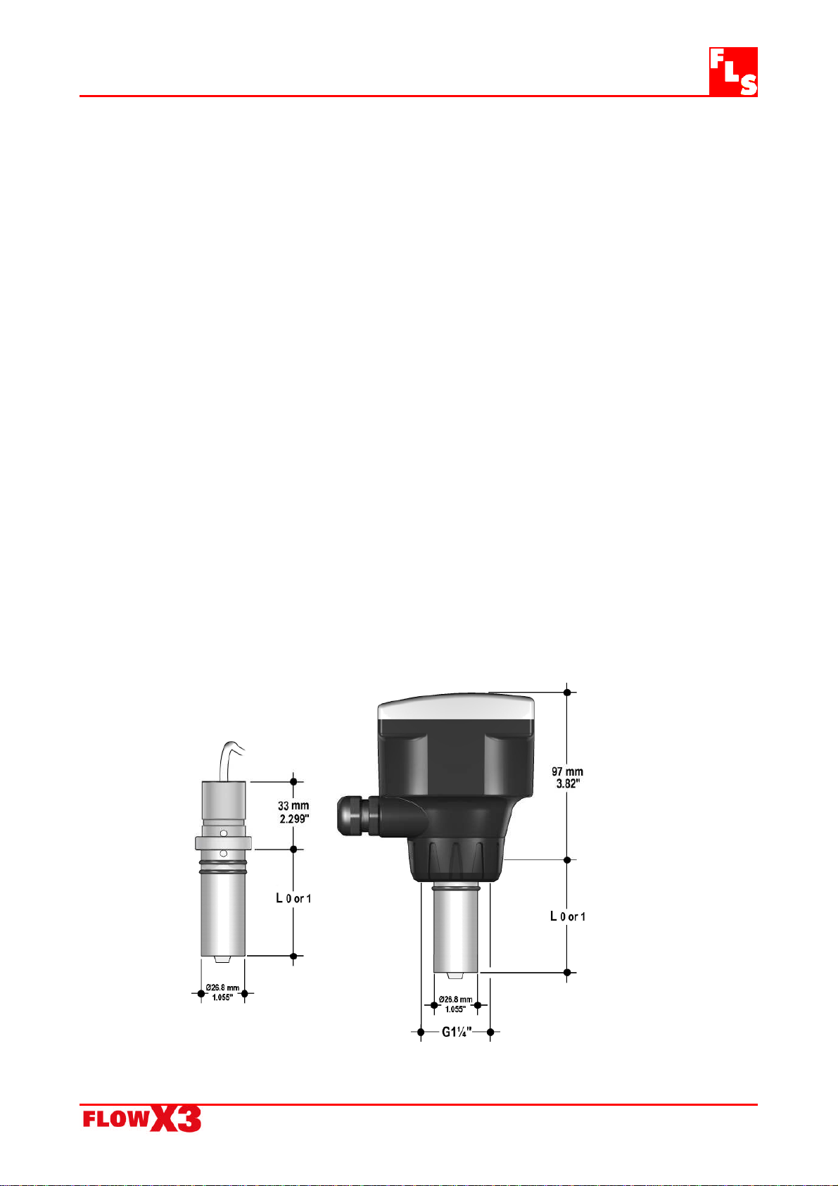
3.2. Dimensions
F9.63 Electromagnetic insertion flow sensor
7
4. Installation
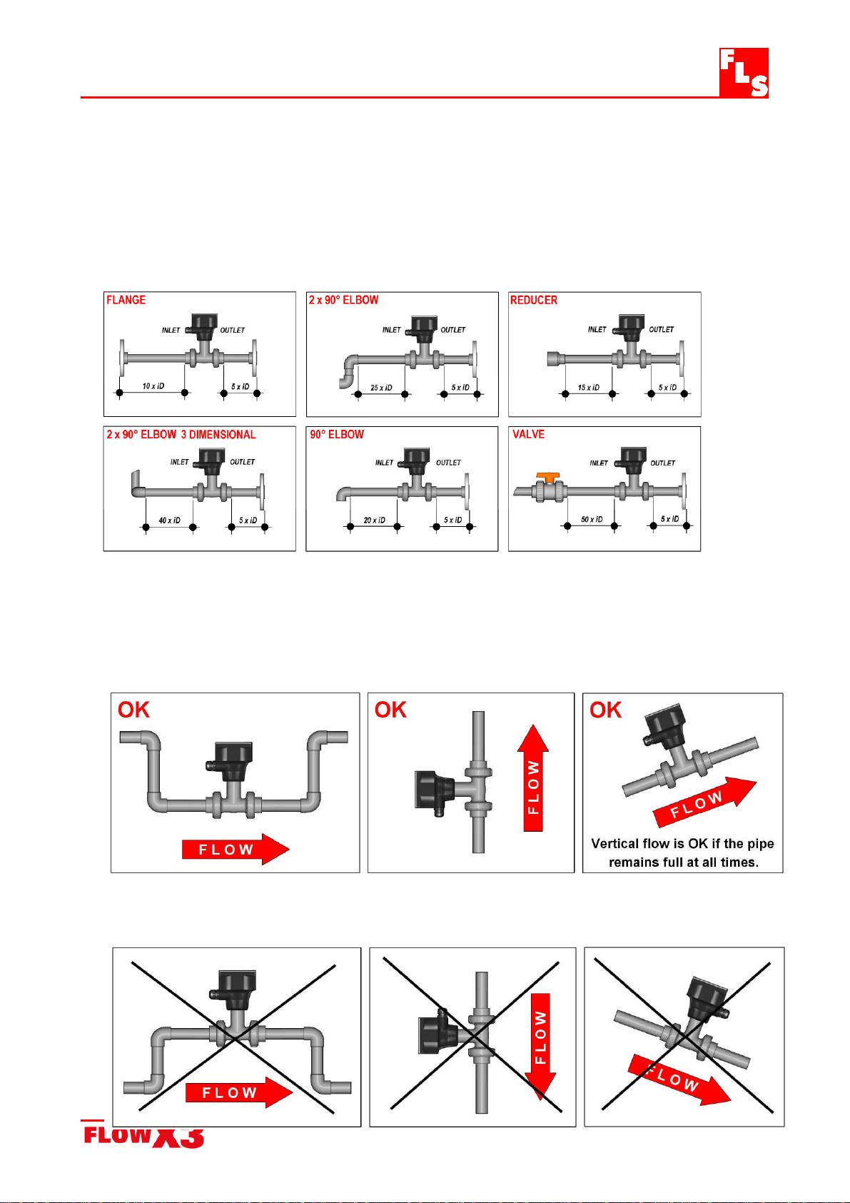
4.1. Location
Different pipe configurations and obstacles in the flow line such as valves, elbows, pipe
bends and strainers create variations on the flow profile.
Whenever possible follow the EN ISO 5167-1 installation recommendations to locate
the sensor.
Always maximize distance between flow sensor and pump.
4.2. Mounting Position
The following configurations ensure that the pipe is always full: for a correct
measurement the sensor can NOT be exposed to air bubbles at any time.
Avoid the following situations unless you are absolutely sure the sensor is not exposed
to air bubbles.

F9.63 Electromagnetic insertion flow sensor
8
In gravity-flow systems the connection to the tank must be designed so the level does
not drop below the outlet: this to avoid pipe to draw air in from the tank causing an
erratic measurement of the Magmeter.
4.4. Wiring
All wiring connections to F9.63 are made via removable terminals. Flow sensor
terminals are orange, all other terminals are green.
General recommendation
Always ensure the power supply is switched off before working on the device.
Terminals accept 26 to 12 AWG (0.08 to 2.5 mm2)
Strip around 10 mm (0.4”) of insulation from the wire tips and tin bare ends to
avoid fraying.
Ferrules are suggested when connecting more than one wire to a single terminal.
Remove the upper part of the terminals for an easy cabling.
Insert wire tip or ferrule completely into the terminal and fix with the screw until
finger tight.
The Magmeter output signal may be unstable immediately after the installation.
Install the sensor in a full pipe for 24 hours will stabilize the performance. With a
very low Electrical Conductivity could be necessary a longer conditioning period.
Use electrical cables with the proper external diameter for the liquid tight
connector:
PG11: external diameter between 2-7 mm (0.079-0.276”)
PG13,5: external diameter between 5-12 mm (0.197-0.472”)

F9.63 Electromagnetic insertion flow sensor
9
Rear Terminal View
Power / Loop Wiring Diagram
Stand-alone application, Connection to a PLC with built-in
no current loop used power supply (3 wire connection)
Connection to a PLC / Instrument with ONE separate power supply
or

F9.63 Electromagnetic insertion flow sensor
10
Connection to a PLC / Instrument with TWO separate power supplies
or
Open Collector Wiring Diagram
Connection to a PLC Connection to a PLC / Instrument
Open Collector input digital input with separate Power Supply
Connection to FlowX3 Instruments
Relay Wiring Diagram
The alarm is OFF during normal operation The alarm is ON during normal operation
and goes ON according to Relay settings. and goes OFF according to Relay settings
This manual suits for next models
1
Table of contents
Other FLS Measuring Instrument manuals


