
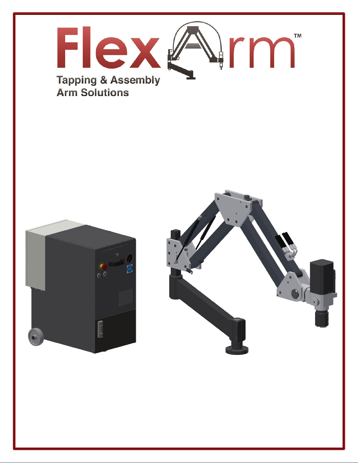
FlexArm GH-24 User manual

1/26/2021 REV. 007 2
TABLE OF CONTENTS:
Safe Operation: READ THIS FIRST - - - - - - - - - - - - - - - - - - - -
3
Warranty - - - - - - - - - - - - - - - - - - - - - - - - - - - - - - - - - - - - - -
4
Specifications - - - - - - - - - - - - - - - - - - - - - - - - - - - - - - - - - -
5-6
Electrical Installation - - - -- - - - - - - - - - - - - - - - - - - - - - - - - -
7
Arm Installation - - - - - - - - - - - - - - - - - - - - - - - - - - - - - - - - -
8-10
Start Up Procedure - - - - - - - - - - - - - - - - - - - - - - - - - - - - - -
11
Shut Down Procedure - - - - - - - - - - - - - - - - - - - - - - - - - - - -
13
Tap Lubricator System - - - - - - - - - - - - - - - - - - - - - - - - - - - -
14
Operator Instructions - - - - - - - - - - - - - - - - - - - - - - - - - - - - -
15
Adjusting Torque Holder Clutch Setting - - - - - - - - - - - - - - -
16
Torque Requirements for Tapping - - - - - - - - - - - - - - - - - - -
17
Multi-Position Head Operating Instructions - - - - - - - - - - - -
18-19
Counterbalance Adjustment - - - - - - - - - - - - - - - - - - - - - - -
20
Parts Breakdown: ARMS - - - - - - - - - - - - - - - - - - - - - - - - - -
21-29
Parts Breakdown: 2-SPEED GEARBOX - - - - - - - - - - - - - - - - -
30-31
Parts Breakdown: ACCESORIES - - - - - - - - - - - - - - - - - - - - - -
32-36
Parts Breakdown: POWER PACK - - - - - - - - - - - - - - - - - - - - -
37-42
Cylinder Replacement - - - - - - - - - - - - - - - - - - - - - - - - - - - -
44-47
Maintenance - - - - - - - - - - - - - - - - - - - - - - - - - - - - - - - - - - -
48-50
Troubleshooting - - - - - - - - - - - - - - - - - - - - - - - - - - - - - - - -
51-54

1/26/2021 REV. 007 3
SAFE OPERATION: READ THIS FIRST
•Read the entire unit manual before operating the machine.
•Do not remove shipping zip tie strap until instructed in this manual.
•Wear eye protection when operating this machine.
•Do not wear jewelry when operating this machine. Tie hair back when using this machine.
•Do not wear gloves when operating this machine.
•Turn off the air supply before adding oil to the filter / lubricator.
•Turn off the air supply before preforming any maintenance operations.
•Hearing Protection is recommended.
•Removing the tool or weight from the arm will allow the arms to extend rapidly possibly causing
damage or injury.
•Keep hands clear of the motor chuck and tap when the motor is running.
•Keep hands clear of pinch points when operating the machine.
•Do not alter or modify the FlexArm.
•Periodically inspect for damage, loose hardware or anything irregular on the FlexArm.
•Preform regular maintenance according to this manual.
•Do not alter or modify the machine.
•Read the FlexArm Limited Warranty before performing any maintenance or repairs.
•FlexArm is not responsible for accident or injury resulting from the misuse of this machine or for use
other than originally designed and intended.
IT IS IMPERATIVE THAT THE TABLE OR MOUNTING SURFACE BE LAGGED TO THE FLOOR AND SECURE BEFORE
INSTALLING THE FLEXARM. Failure to secure the table or mounting surface could result in serious injury to the
operator as well as the FlexArm.
•The oil hoses & fittings are rated for a maximum operating pressure of 180 Bar.
•The normal operating pressure of the unit is between 100 and 120 Bar.
•The workpieces must be firmly held in place to avoid breakage of taps or to strike the operator. The
operator doesn't have to wear special clothing, but protection glasses must be worn.
•When the machine is installed, connect it to the ground clamp system before operating.
•For every adjustment to this machine, the master switch must be disconnected, and the work carried
out by licensed electricians.

1/26/2021 REV. 007 4
FLEXARM LIMITED WARRANTY
What does a FlexArm Warranty Cover
The repair or replacement of the FlexArm product if it is found to be defective due to faulty materials,
workmanship or function within the guarantee period of 1 year. The warranty is based off normal
usage, or equivalent to a 40-hour work week. Claims within the first 90 days will be handled under a
direct return and replace policy. Freight can be credited up to $500.00 upon a positive warranty claim.
What is not covered by a FlexArm Warranty
FlexArm Inc shall not be liable for costs of repair or replacement of a product incurred as a result of:
•A FlexArm product that has had the serial number altered or removed.
•Cylinders with scratches or marks on the shaft.
•Handling of the product which is not in accordance with the product manual.
•Damage as a result of using the unit over its stated capacities.
•FlexArm products not purchased direct or from an authorized dealer.
•Use of parts and accessories other than those produced or recommended by FlexArm.
•Improper maintenance or lack of maintenance per the manual.
•Damage from external sources such as transit, weather, electrical outages, power surges, or bad
air quality (compressor).
•Repairs or alterations carried out by parties other than FlexArm or its authorized distributors.
•Tap Holders and Helicoil components do not carry a warranty.
In Air Motors: Filters, Springs, Blades/Vanes, O-Rings are not covered.
Warranty Service
Before service can take place, the terms of the limited warranty require that you contact FlexArm with
your model, serial number, and date of purchase. Please keep your purchase receipt in a safe place to
ensure you have this information. The serial number is found on the FlexArm’s side plate.
•An RGA must be obtained from a FlexArm Customer Service Representative.
•All work will be coordinated by FlexArm or its authorized distributors.
•Any replaced defective parts must/will become the property of FlexArm.
Service under this warranty will not extend the period of this warranty. If your FlexArm is not
functioning properly, please call FlexArm at 1-800-837-2503. Most issues can be rectified over the
telephone by our trained Customer Service Department.

1/26/2021 REV. 007 5
SPECIFICATIONS
TECHNICAL DETAILS CHART
MODEL
GH-24
GH-30
GH-45
GH-60
Electric Motor (HP)
5.5
5.5
5.5
5.5
Operating Pressure (Bar)
120
120
120
120
Min Thread Capacity
#6
#6
1/4"
1/4"
Max Thread Capacity
7/8"
1-1/4"
1-1/2"
2"
RPM
100-500
140-500
110-500
55-275
Oil Tank Capacity (Gallons)
9
9
9
9
Max Torque (lbf-ft)
78/63
188/63
325/63
811/162
1/26/2021 REV. 007 6
SPECIFICATIONS
Hydraulic Oil:
•This unit has been factory tested and ships with hydraulic oil in the tank. The tank holds a maximum of
9 gallons of hydraulic oil. Check the oil level on the oil level/temperature gauge on the front of the
power pack.
•The following (ISO Grade 46 compatible) hydraulic oils are recommended for use in the FlexArmTM
Hydraulic Tapping Machines:
Hydraulic Oils
Brand Name
Manufacturer
Energol HLP-46
BP
DTE 25
Exxon Mobil
NUTO HP 46
Exxon Mobil
Tellus 46
Shell Oil Corporation
Hyspin AWS 46
Castrol
Rando HD ISO 46
Chevron
WARNING!
Do not operate the machine if the oil level is BELOW the RED DOTTED LINES on the oil level gauge.
Do not add oil while the machine is operating. First, turn off the machine, disconnect the power supply, and
allow the unit to cool down to 80 degrees or less before adding hydraulic oil.
To add oil, unscrew the cap on the oil tank at the back of the power pack. Using a funnel with a flexible spout,
pour the oil slowly into the tank and check the oil level/temperature gauge as it is being added. DO NOT FILL
ABOVE THE BLACK DOTTED LINES AT THE TOP OF THE OIL LEVEVTEMPERATURE GAUGE.

1/26/2021 REV. 007 7
ELECTRICAL INSTALLATION
1. Check the voltage your unit is wired for, either 220V or 480V. This will be indicated on the electrical panel
on the rear of the Power Pack unit. An example of a 480V unit is shown below, with the voltage sticker
next to the master switch.
2. Connect the machine to a grounded, 3 phase electric supply. The circuit should be protected with a 20
amp circuit breaker if it is wired for 480v and 30 amps if it is wired for 220v. The unit does not come with a
plug.
CAUTION: When making repairs to this unit, always disconnect the main power supply. Additionally,
hooking up an incorrect power supply could result in damage to the unit and void any existing warranty.

1/26/2021 REV. 007 8
ARM INSTALLATION
1. Drill and tap four bolt holes on a flat, smooth table or workbench. Use 3/8-16 bolts for the 24, 30, and
45 series units. Use 1/2-13 bolts on the 60 series units. (See Base Mount diagram below)
Base Mount Patterns
GH-24, GHM-24, GH-30
GHM-30, GH-45, GHM-45
GH-60, GHM-60
2. Secure the base mount and apply a light coating of grease to the base mount shaft. Slide the angle
mount onto the shaft of the base mount and secure the angle before inserting the FlexArmTM! (See
Angle Mount Assembly Diagram Below)

1/26/2021 REV. 007 9
ARM INSTALLATION
3. Secure the angle mount by placing the washer on top of the lower bore and tightening the angle
mount bolt securely into the base mount for a GH-24 and GH-30. For the GH-45 and GH-60, tighten the
two angle mount screws. The angle mount bolts must be tightened securely, or the machine will not
maintain perpendicularity.
4. Insert the rear pin of the unit into the upper bore and bearing of the angle mount. The rear pin may
not slide through both bearing sets- use the flathead cap screw to help pull the unit entirely through
the bottom bearing
5. Remove any straps holding the arms together and adjust the counterbalance of the arm. This will
eliminate the possibility of the arm striking the operator when it is positioned at its lowest point. (See
Counter Balance Adjustment Section on page 21)

1/26/2021 REV. 007 10
ARM TO POWER PACK INSTALLATION
1. After the FlexArm is securely fastened to its mounting surface, it can be hooked up to the power pack.
2. First, connect the two hydraulic hoses on the arm to the quick-disconnect hose couplings on the power
pack. There should be a male and female fitting.
3. Next, attach the male four-pin connector on the arm to the left female receptacle on the power pack.
There should be a locking clip on the female receptacle, notating the proper one to attach to.
4. The four-pin female connecter on the right is only to be used with arms adapted with digital depth
control (Instructions for digital depth control are found in a separate manual).
5. Lastly, the airline can be connected to the regulator-manometer shown on the far left of the image
below. This is to be used with units that have the semi-tap lubricator option.
Other manuals for GH-24
1
This manual suits for next models
7
Table of contents
Other FlexArm Industrial Equipment manuals











