Field Scout TDR 150 User manual

TDR 150
Soil Moisture Meter
PRODUCT MANUAL
Item # 6445
Distributed & Supported By:
www.edaphic.com.au
Ph: 1300 430 928

2
CONTENTS
Meter Dimensions 4
Batteries 5
Button Functions 7
Display Screens 9
Meter Calibration 13
Updating Firmware 14
Adding GPS/Bluetooth Capability 15
Electrical Conductivity 17
Meter Operation 19
Replacing or Re-attaching the Probe Block 22
VWC Measurements 23
GPS Status 24
Field Scout Mobile App/SpecConnect 25
Data Logs 27
Specifications 29
Optional Accessories 30
Appendix 1: Soil-Specific Calibration 31
Appendix 2: Checking VWC Readings 33
Appendix 3: FAQ 34
This manual will familiarize you with the features and operation of
your new Field ScoutTM TDR 150 Soil Moisture Meter. Please read
this manual thoroughly before using your instrument.

3
Thank you for purchasing the Field ScoutTM TDR 150
soil moisture, electrical conductivity and soil surface
temperature meter. This manual describes the meter's
general features and operation.
Soil moisture is a critical, and potentially highly varia-
ble, component of the soil environment. Time domain
reflectometry is a proven technology for quickly and
accurately determining volumetric water content
(VWC) in soil. Electrical conductivity (EC) is a func-
tion of the moisture and salt in the soil. The meter also
measures soil surface temperature. The user can quickly
transition between taking VWC readings in standard
and high-clay mode.
The TDR 150's probe connects to the display with an
11.5 inch cable. This allows the user to take measure-
ments in a field, sports surface, or greenhouse bench.
The meter can be upgraded (item 6445GBU) to activate
the built-in data logger and GPS. This eliminates the
need to record data manually. The data points can be
viewed with the FieldScout Mobile app that maps out
soil measurements using logged GPS locations. Meas-
urements can also be saved to a USB drive that is
plugged into the built-in USB port.
Contents
Your shipment includes the following components:
-TDR 150 meter
-Carrying case
-4 AA batteries
Note: TDR rods are sold separately
General overview
4
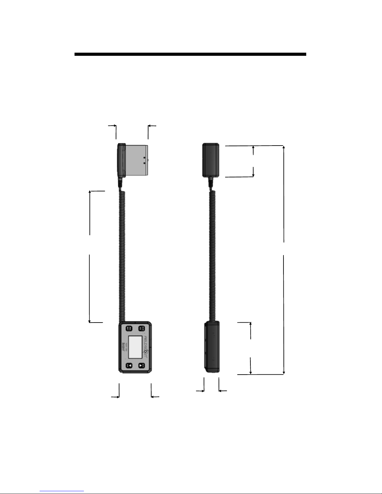
Meter dimensions
3.00 in
5.15 in
11.5 in
3.30 in
3.00 in
1.50 in
23.0 in

5
Changing the batteries
The TDR 150 requires 4 AA batteries. The battery
holder is on the underside of the display unit. Re-
move the screws and take off the base plate. Install
batteries and ensure correct polarity by referencing
the (+) positive and (-) negative labels at either end
of each slot. Replace the base plate. Be sure the
sensor is still plugged into the socket (see fig. 1).
Do not permanently remove the foam plug (fig.
2). It ensures the plug does not come detached.
Batteries
cable
Fig. 1: Sensor Cable attached.
Fig. 2: Foam plug installed

6
Battery life
The battery level is checked
every time the display unit is
turned on. If the battery level
is low, or if a battery is in-
serted incorrectly, this low battery image shows on
the full screen for about 10 seconds and the dis-
play will automatically turn off.
In addition to frequency of use, battery life is im-
pacted by use of the backlight and GPS receiver
(for upgraded units). If not needed, the GPS fea-
ture should be disabled. The backlight can be set to
AUTO mode (p. 11). This allows enough time to
see the reading without unduly taxing the battery.
Total Readings
Bluetooth*GPS*Backlight Alkaline Lithium
ON ON ON 12,000 24,000
ON ON OFF 24,000 35,000
OFF OFF OFF 150,000 225,000
* GPS and Bluetooth capability is an option acces-
sory for the TDR 150 meter (see p. 15)

7
Button Functions
Basic Button Operations
ON/OFF or BACK button
Press this button briefly to turn on the
display. The meter will then display
the Data screen (p. 10). To turn the
meter off, press and hold this button
for about 2 seconds.
When in the Settings Menu screen (p. 11), press
this button to return to the Data screen. If you are
in a settings option that requires its own screen,
this button will return you to the Settings Menu
screen
MENU or SELECT button
When in the Data screen, press this but-
ton to go to the Settings Menu screen
(p. 11). When in the Settings Menu
screen and on a menu option, press this
button to browse through the different
choices for that specific menu selection.
In some cases, selecting a settings option will take
you to another screen for further action.

8
DELETE or UP button
When on the Data screen (p. 10), press
this button to delete the last measured
data point from the both the log file
and the computed Average. The Delete
button also decrements the Count.
When on the Settings Menu screen (p. 11), press
this button to scroll up to the previous menu item.
READ or DOWN button
When on the Data screen, press and
release this button to take a sensor
reading. Press and hold to clear the av-
erage and reset the sample count to 0.
Pressing and holding the READ button
also adds a blank line to the data file.
When on the Settings Menu screen, press this but-
ton to scroll down to the next menu item.

9
Display Screens
The TDR 150 has 3 main display screens;
- Startup Information screen
- Data screen
- Settings Menu screen
Startup Information screen
The Startup Information screen is displayed for
about 2 seconds after the display is turned on.
If desired, the startup screen can be kept on for a
longer duration. While powering up the meter,
press and hold the On/Off/Back button to contin-
ue displaying the Startup Device Information
screen. Release the button to proceed to the Data
screen.

10
Data screen
Readings from
the sensor are
displayed on the
Data screen. The
battery level in-
dicator appears
in the upper right
corner. The run-
ning average and
number of readings included in that average are
shown in the lower right corner. Pressing and
holding the READ button will clear the average
and re-set the counter to 0.
If the meter has been
upgraded to add GPS
and Bluetooth capa-
bility (see p. 15),
these icons will appear next to the battery indica-
tor. When visible, the GPS icon will indicate the
quality of the GPS fix (p. 24).
When the Bluetooth is enabled, but the TDR is
not connected to a mobile device, the Bluetooth
icon has a bar through it (see image to the left).
When the TDR is connected to a mobile device,
the bar is removed (see image to the right).
When disabled in the Settings Menu (p. 11), the
GPS and/or Bluetooth icons will no longer be vis-
ible.
Table of contents
Other Field Scout Measuring Instrument manuals


