
Elster Instromet RVG User manual

Instruction Manual
Rotary Gas Meters
Type RVG · RVG-ST
Betriebsanleitung
Drehkolbengaszähler
Typ RVG · RVG-ST
Mode d’emploi
Compteur de gaz à pistons rotatifs
Type RVG · RVG-ST
Manual de instrucciones
Contador de gas de pistones rotativos
Modelos RVG · RVG-ST
Istruzioni d’uso
Contatore gas a pistoni rotanti
Tipo RVG · RVG-ST
Installatie voorschrift
Rotorgasmeters
Type RVG · RVG-ST
Elster GmbH
Steinern Straße 19 · 55252 Mainz-Kastel
Tel. +49 (0)6134/605-0 · Fax +49 (0)6134/605-390
www.elster-instromet.com
73019203f/04.2009/A P&M

1© Elster GmbH · All rights reserved · Subject to technical modification
English
Elster-Instromet
Deutsch
Nederlands Italiano Español Français
Instruction Manual
Rotary Gas Meters
Type RVG · RVG-ST
Betriebsanleitung
Drehkolbengaszähler
Typ RVG · RVG-ST
Mode d’emploi
Compteur de gaz à pistons rotatifs
Type RVG · RVG-ST
Manual de instrucciones
Contador de gas de pistones rotativos
Modelos RVG · RVG-ST
Istruzioni d’uso
Contatore gas a pistoni rotanti
Tipo RVG · RVG-ST
Installatie voorschrift
Rotorgasmeters
Type RVG · RVG-ST

2© Elster GmbH · All rights reserved · Subject to technical modification
Elster-Instromet

3© Elster GmbH · All rights reserved · Subject to technical modification
English
Elster-Instromet
RVG G16-G400
RVG-ST G10-G25, threaded version RVG-ST G10-G25, flanged version
Instruction Manual
Rotary Gas Meters
Type RVG · RVG-ST

4© Elster GmbH · All rights reserved · Subject to technical modification
Elster-Instromet

5© Elster GmbH · All rights reserved · Subject to technical modification
English
Elster-Instromet
Contents
1. Staff .......................................................................................................................... 06
2. Legal Declarations .................................................................................................... 06
3. Intended Use and Field of Application ..................................................................... 57
4. Technical Data .......................................................................................................... 08
5. Operating Location ................................................................................................... 09
6. Installation Position, Flow Direction and Wall Clearance ......................................... 09
7. Installation / Connection......................................................................................... 111
8. Lubrication and Maintenance ................................................................................... 13
9. Commissioning ......................................................................................................... 15
10. Function Check ........................................................................................................ 16
11. Pulse Generators ...................................................................................................... 16
12. Pressure Test Point .................................................................................................. 18
13. Temperature Test Points .......................................................................................... 18
14. Index Versions .......................................................................................................... 19
15. Absolute ENCODER S1D ......................................................................................... 20
16. Care and Cleaning .................................................................................................... 21
17. Recycling and Environmental Protection ................................................................. 21
18. Annex A (ATEX Approvals) ....................................................................................... 22
19. Annex B (Plastics Used) ........................................................................................... 23
20. Annex C (Declaration of Conformity) ........................................................................ 24

6© Elster GmbH · All rights reserved · Subject to technical modification
Elster-Instromet
1. Staff
2. Legal Declarations
These Instructions are aimed at staff who have adequate specialist and technical
knowledge (in Germany, for instance, in accordance with DVGW Codes of Practice 492 and
495 or comparable technical regulations) on the basis of their training and experience in the
sector of energy and gas distribution.
–Declaration of Conformity – see Annex C.
–Period of validity of calibration – this is based on the regulations of the country concerned,
in which the rotary gas meter will be used.
–The calibration of rotary gas meters is only valid for the period of validity of calibration.
Once this has elapsed, rotary gas meters may no longer be used for purposes which are
subject to obligatory calibration.
7© Elster GmbH · All rights reserved · Subject to technical modification
English
Elster-Instromet
3. Intended Use and Field of Application
This product is intended
for calibratable volumetric metering of
–flammable gases: natural gas/town gas/butane,
–non-flammable gases: air/nitrogen/inert gases,
–and is suitable for use in potentially explosive atmospheres of Category 2 (Zone 1) of
Class EX II 2 G c IIC.
Other fields of application / media on request.
This product is not intended for
–metering of aggressive gases, e.g. biologically produced methane or sewage gases,
oxygen, acetylene.
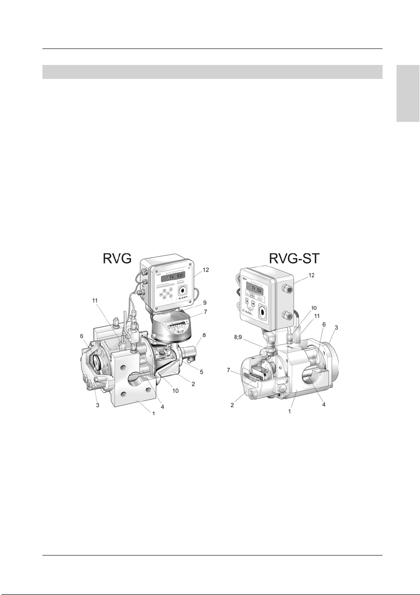
1Meter housing 17Index head
2Housing cover (front) 18HF pulse generator
3Housing cover (rear) 19LF pulse generator
4Pistons 10 Pressure test point
5Gear assembly 11 Temperature test point
6Synchronising gears 12 Volume corrector (optional)
Please contact your Elster-Instromet Customer Service (Tel. +49 (0)6134-605-0 / -346)
for assistance in commissioning, maintenance and installation of encoders, pulse generators
and volume correctors for instance.

8© Elster GmbH · All rights reserved · Subject to technical modification
Elster-Instromet
4. Technical Data
Rotary gas meters in accordance with DIN EN 12480
Type RVG-ST RVG
Size: G10 to G25 G16 to G400
Nominal diameter: DN 25 to DN 50 DN 40 to DN 150
Pressure ratings: PN 10/16 or CLASS 150
Temperature ranges:
– gas / ambient / storage -20 ˚C to +60 ˚C*
– gas / ambient / storage (MID) -10 °C to +55 °C-25 ˚C to +55 ˚C*
Housing material: Aluminium Spheroidal graphite
cast iron or aluminium
Mechanical ambient conditions: M1
*Measuring ranges ≥1:130, -10˚C
Pulse generators
LF pulse generator E1 Wiegand pulse generator HF pulse generator
(reed contact) (in accordance with
DIN EN 50227)
Umax = 24 V Umax = 30 V Urated = 8 V DC
Imax = 50 mA Imax = 100 mA I 욷2.1 mA (exposed)
I 울1.2 mA (covered)
Pmax = 0.25 VA Pmax = 600 mW U 쏝5.9 V (exposed)
U 쏜6.8 V (covered)
Ri= 100 Ω(series resistor) Ri= 1 kΩ
Absolute ENCODER S1D
Absolute ENCODER S1D
Index
Number of indexes 2
Number of digit rollers per index 8
Safety class IP 67
Interfaces NAMUR (II 2 G EEx ia IIC T4) or
ATEX approval SCR / SCR Plus (II 2 G EEx ib IIB T4) or
M-BUS
LF pulse generator Optional or retrofittable INS-10, -11, -12
Umax = 24 V, Imax = 50 mA, Pmax = 0.25 VA,
Ri= 100 Ω(series resistor)

9© Elster GmbH · All rights reserved · Subject to technical modification
English
Elster-Instromet
5. Operating Location
6. Installation Position, Flow Direction and Wall Clearance
If you …
–wish to mix in odorisation agents or
– use solenoid valves,
please always fit them only downstream of the meter. Otherwise, the device may be
damaged.
The flow through the meter must be free of vibrations / pulsations in order to avoid
measuring errors.
Compliance with the specified operating and ambient conditions as indicated on the type
label is absolutely essential for safe operation of the meter and additional equipment.
The gas may not contain suspended particles > 50 m. In addition, the gas must be dry.
Otherwise, the meter may be damaged.
To protect the meter, a coarse filter (cone strainer with mesh size 250 m) must be installed
on all new installations, and is also recommended for existing installations. The strainer
should be removed after approximately 4 to 6 weeks.
Type RVG:
Gas can be passed through the Type RVG rotary gas meter both horizontally and vertically.
The index head can be turned through up to 355°for optimum ease of reading in different
installation/operating positions. If the meter is equipped with oil-level gauge glasses on just
one side, then the meter must be mounted with a gap (욷B + 30 mm) from the centre of the
pipe to the wall, in order to facilitate access for maintenance (Figure 1 and Table 1):
Figure 1: Horizontal flow from left to right and from right to left
Wall Wall
This manual suits for next models
1
Table of contents
Languages:
Other Elster Instromet Measuring Instrument manuals


