Dilog CombiVolt DL6780 User manual

DL6780/DL6790 CombiVolt™
Voltage & Continuity Indicator
Voltage Indication 12 - 690V
AC/DC with Continuity
Instruction Manual
EN
61010-1
CAT IV
600V

DL6780/90 Operating Manual
Di-LOG
...measurably better
Contents
I. Overview 3
II. Safety Notice 3/4
III. Instrument Symbols 5/6
IV. Technical Specication 6
V. Display and Controls 7
1. Operating Instructions 7
2. AC Voltage Indication 8
3. DC Voltage Indication 9
4. Single Pole Voltage Indication 10
5. Continuity 11
6. Phase Sequencing Indication 11/12
7. Maintenance 13
8. Battery Replacement 13
9. Calibration 13
10. Accessories 14
11. Warranty Information 14
1

DL6780/90 Operating Manual
Di-LOG
...measurably better
Certicate of conformity
As the manufacturer of the instrument listed
below, we declare under our sole responsibility
that the product:
Di-LOG DL6780/DL6790
to which this declaration relates is in conformity
with the relevant clauses of the following standards:
EN 61010-1:2010
EN 61010-2-030:2010
EN 61010-031:2015
EN 61243-3:2014
EN 61326-1:2013
EN 61326-2-2:2013
IEC 60529 (IP65)
LVD & EMC
The safety and performance of this instrument is
assured when operated within the specications
in this instruction manual.
The product identied above conforms to the
requirements of council directive 2014/35/EU
2

DL6780/90 Operating Manual
Di-LOG
...measurably better
I. Overview
Thank you for purchasing a Di-LOG voltage continuity
tester. This tester has been designed in accordance
with the latest international safety standards.
The CombiVolt™ series of instruments are fully
automatic voltage indicators capable of measuring AC/
DC voltage up to 690V. Both units have visual and
acoustic continuity indication, single pole detection
and a phase rotation sequencing indication.
Constructed in accordance with IEC 61010-1 and
IEC 61243-3.
• Single pole phase indication
• 2 pole phase rotation indication
• LED & LCD display (DL6790).
3
II. Safety Notices
This instruction manual contains information that must
be followed for operating the meter safely and main-
taining the meter in a safe operating condition. If this
meter is not used in the manner that is specied, the
protection provided may be impaired.
Warning! Warns of potential danger, refer to the
instruction manual to avoid personal injury or damage
to the meter.
Caution! Dangerous voltage. Danger of electrical
shock.
Perfect display is only guaranteed within a temperature
range of -10 - 50°C, relative humidity <85%.
A statement about protection impairment if used in
a manner not specied by the manufacturer.
The voltage indicators are designed to be used by
skilled persons and in accordance with safe methods
of work.
The voltages marked on the voltage indicator are
nominal voltages and the voltage indicator is only to
be used on installations with the specied nominal
voltages.
The dierent indicating signals of the voltage indicator
are not to be used for measuring purposes.
Before using a voltage indicator at locations with a
high background noise level, it has to be determined
whether the audible signal is perceptible.

DL6780/90 Operating Manual
Di-LOG
...measurably better
4
II. Safety Notices (continued)
It is important to check the state of the battery before
use and to replace it if necessary.
The meter has been designed in accordance
with the safety regulations for electronic
measuring instruments, EN 61010-1:2010,
EN 61010-2-030:2010, EN 61010-031:2015, EN
61243-3:2014, EN 61326-1:2013 & EN 61326-
2-2:2013
Voltages above 75V DC or 50V AC may constitute a
serious shock hazard.
Before using the meter, check for physical damage to
the casing, in particular around the cable strain relief.
If the case is damaged, do not use the meter.
Check the test probes for damaged insulation or
exposed metal.
Check the leads for continuity.
Do not apply more than the rated voltage, as marked
on the meter between the terminals or between any
terminal and ground.
Do not use or store the meter in an environment of
high temperature, humidity, fumes, vapour, gaseous,
inammable, and strong magnetic eld.
The performance and safety of the instrument and the
user may be compromised in such circumstances.
Disconnect circuit power and discharge all high voltage
capacitors before testing resistance, continuity and
diodes.
Remove the batteries if the meter is not in use for a
long period.
Constantly check the battery as it may have leaked. A
leaking battery will damage the meter.
The meter may only be opened by a qualied service
technician for calibration and repair.

DL6780/90 Operating Manual
Di-LOG
...measurably better
Warning! Warns of potential danger, and to
comply with the instruction manual.
Caution! Dangerous voltage, potential risk
of electrical shock.
Equipment protected throughout by double
or reinforced insulation. Complies with IEC
536, class II
Suitable for live working
CE Symbol of conformity conrms conformity
with relevant EU directives. The meter
complies with EMC directives (2004/ 1 08/
EC), the Low Voltage Directive (described
in the standard EN 61010·1, 61243·3.
The DL6780/90 meets the standard
(2012/19/EU) WEEE. This marking
indicates that this product should not be
disposed with other household wastes
throughout the EC. To prevent possible
harm to the environment or human health
from uncontrolled waste disposal, recycle
it responsibly to promote the sustainable
reuse of material resources. To return your
used device, please use the return and
collection systems or contact the retailer
where the product was purchased. They
can take this product for environmental safe
recycling.
The instruction manual contains information
and references, necessary for safe opera-
tion and maintenance of the instrument.
Prior to using the instrument the user is
kindly requested to thoroughly read the
instruction manual and comply with it in all
sections.
5
III. Instrument & Manual Symbols
Symbols displayed on the instrument and in the
instruction manual:

DL6780/90 Operating Manual
Di-LOG
...measurably better
III. Instrument Symbols (continued)
IV. DL6780/DL6790 Specication
6
CAT IV Applicable to test and
measuring circuits connected at the
source of the building’s low-voltage
MAINS installation.
Failure to read the instruction manual or
to follow the warnings and references
contained herein can result in serious bodily
injury or instrument damage. The respective
accident prevention regulations established
by the professional associations are to be
strictly enforced at all times.
EN
61010-1
CAT IV
600V
DL67xx Voltage Indicator Specification
DL6780 DL6790
2 Pole Voltage Indication
Voltage range 12 - 690V AC/DC
LED resolution 12, 24,50, 120, 230, 400 & 690V
LCD resolution n/a 1 V +/- 3 % + 8 digits
Voltage detection Automatic
Frequency range 0 - 400Hz
Peak current 3.5mA
Operation time 30 Seconds
Acoustic AC/DC signal
Auto power on >12V AC/DC
IP rating IP65
Single Pole Indication
Voltage range 100 - 690V AC
Frequency range 50 - 400Hz
Continuity
Acoustic & visual
Measurement range 0 - 400kΩ
Phase Rotation Test
Voltage range 100 - 690V AC
Frequency 45 - 65Hz
Over voltage protection 690V AC/DC
Other Information
Dimensions 225mm x 70mm x 28mm
Weight (net) 200g 210g
Power supply 2 x 1.5V (RO3) AAA (supplied)
EAN 5060082542329 5060082542336

DL6780/90 Operating Manual
Di-LOG
...measurably better
1. Operating Instructions
Carrying out measurements
Perform a self-test of the unit. Connect the two
test probes L1 and L2 together. The continuity
LED (6) will be lit, and an audible tone should be
heard.
Before any test, check the unit on a known
voltage source or approved voltage proving unit.
If the unit is defective it should be put out of service
and returned to Di-LOG for repair.
7
V. Display and Controls
1. Test Probe (-) L1
2. Test Probe (+) L2
3. LED’s for voltage indication
4. LED for single - pole test
5. Right & Left LED, phase rotation indication
6. LED for continuity
7. LCD for voltage display (only DL6790)
8. Contact electrode for double-pole test of
phase rotation and single-pole test
9. Torch button on the back
10. Positive LED
11. Negative LED
12. Battery Compartment

DL6780/90 Operating Manual
Di-LOG
...measurably better
2. AC Voltage Indication
8
Always hold the test probes by the handles
behind the nger guards. Observe all the safety
notices at all times.
An audible tone is present when an AC voltage
and a negative DC voltage are indicated.
The maximum switch on time is 30 s. When this
time has elapsed, you must wait 10 minutes
before retesting.
Connect probes to the voltage source observing
the polarity of the test probes, L2 is the positive
probe, L1 is the negative probe.
For AC voltage the value is indicated on the
LEDs (3) and on the LCD display (DL6790 only).
The + and - LEDs are illuminated and buzzer is
audible.
DL6780/90 Operating Manual
Di-LOG
...measurably better
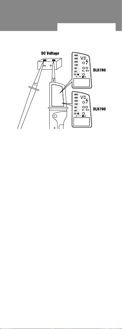
3. DC Voltage Indication
For DC voltage measurement, connect probe
L2 to the positive terminal and L1 to the negative
terminal. The voltage is displayed on the LEDs
and the LCD display (DL6790 only). The positive
LED (10) is illuminated. If the polarity is reversed
the buzzer will sound. The negative LED (11) will
be illuminated.
9
This manual suits for next models
1
Table of contents
Other Dilog Measuring Instrument manuals

Dilog
Dilog DL6799 User manual

Dilog
Dilog DL7040 User manual

Dilog
Dilog DL6506 User manual

Dilog
Dilog DL6702 User manual

Dilog
Dilog DL6780 Combi Volt 1 User manual

Dilog
Dilog DL6507 User manual

Dilog
Dilog DL7206 User manual

Dilog
Dilog DL7030 User manual

Dilog
Dilog PL107N User manual

Dilog
Dilog DL6519 User manual


