
Clas Ohlson UT203 User manual

EnglishSvenskaNorskSuomi
Clamp Ammeter
Tångamperemeter
Tangamperemeter
Pihtiampeerimittari
Art.no Model
36-4718 UT203 Ver. 201201

2
English
Clamp Ammeter
Art.no 36-4718 Model UT203
Please read theentire instruction manual before use and save it for future reference.
Wereserve theright for any errors in text or images and for making any necessary
technical changes to this document. Ifyou should have any questions concerning
technical problems please contact our Customer Services.
Table of Contents
1. Description ................................................................4
2. Safetyinstructions ....................................................4
2.1 International symbols ............................................................ 5
3. Package contents .....................................................6
4. Description ................................................................6
4.1 Functions ................................................................................ 6
4.2 Display symbols ..................................................................... 8
4.3 The function buttons can be used in thefollowing modes .. 9
5. Operation ..................................................................9
5.1 Voltage measurement (V DC) or (V AC) ................................. 9
5.2 Measuring resistance (Ω) ..................................................... 10
5.3 Diode testing ........................................................................ 11
5.4 Continuity test ...................................................................... 12
5.5 Frequency measurement ..................................................... 12
5.6 Duty Cycle measurement .................................................... 13
5.7 AC or DC current measurement .......................................... 13
5.8 Automatic shut-off feature................................................... 14

3
English
6. Changing batteries .................................................14
7. Cleaning ..................................................................15
8. Disposal ..................................................................15
9. Specifications .........................................................15
9.1 General Specifications ......................................................... 15
9.2 Operating environment ........................................................ 16
9.3 Electrical specifications ....................................................... 16
9.4 Example on accuracy .......................................................... 19

4
English
1. Description
• Advanced True RMS clamp-onmeter
• AC, DC, capacitance, resistance and frequency measurements, diode test
andbuzzer
• Automatic shut-off
• Rubber-clad shock-absorbent casing
• Comes with test leads and 9 V battery
• Max jaw opening 28mm
• Size 208×76×30mm
2. Safetyinstructions
• This meter is designed and tested to conform to IEC 61010–1, installation
category (overvoltage category) II 600 V, III 300 V and pollution category II.
• This meter conforms to thefollowing EMC Directives: 89/336/EEC
(EMCNovember 1992, electromagnetic compatibility), Low-Voltage Directive
73/23/EEC, EN61010-1 (04, 93).
• This meter is designed for indoor use at working temperatures in therange
of0–40 °C.
• Read all thesafety information and operating instructions and only use themeter
as specified in this manual.
• Do not use this meter if it or thetest leads appear to be damaged, or if you
suspect that themeter might not work properly.
• Make sure that your fingers are behind thefinger guards when using thetestleads.
• Make sure that thepower is turned off before working on thepower circuit as
even small currents can be dangerous.
• Do not measure voltages over 600 V DC or 600 V AC RMS between apower
point and earth connection.
• To avoid shocks you need to be CAREFUL when you work with voltage higher
than 60 V DC or 30 V AC RMS. Voltages higher than this pose arisk of heavy
electric shocks.
• Set therotary selector switch to thecorrect range and function before starting to
take readings. Thefunction must not be changed during ameasurement.
• Never use themeter if thebattery cover or battery compartment isopen.
• To avoid electric shocks and damage to themeter, do not exceed themeter’s
overload limits. Theguarantee will not apply if themeter is used incorrectly.
• This meter is protected by fuses, but they will not protect themeter from all
kinds of misuse.
• The meter must not be used in humid, explosive or flammable environments or
close to strong magnetic fields.
• Replace thebattery immediately if thebattery warning symbols appears on
thedisplay. Aweak battery can cause incorrect results and thereby pose
asafety hazard.

5
English
• Neither themeter nor its accessories may be dismantled or modified in anyway.
• This meter is only intended for indoor use.
• Remove thebattery from themeter if it is not to be used for anextended period.
• Turn themeter off afteruse.
• If themeter is placed close to astrong magnetic field it might cause incorrect
readings which can be corrected by removing thecause of theinterference.
• Never measure current with thetest leads plugged into any of theinput terminals.
• To avoid damaging themeter, never exceed themaximum input values of
themeasuring data.
• Be very careful when working close to uninsulated conductors. Touching alive
cable or conductor can give you anelectric shock.
• Only use themeter theway described in this instruction manual.
2.1 International symbols
AC (alternating current)
DC (direct current)
AC orDC
Earthconnection
Doubleinsulated
Readthemanual before use
Lowbattery warning
Continuity test (buzzer)
Diode
Fuse
EU standard compliant
6
English
3. Package contents
• Clamp Ammeter
• 9 V battery
• Carrying strap
• Test leads (1 pair)
• Instruction manual
• Storage case
4. Description
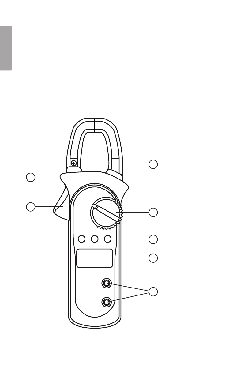
4.1 Functions
2
3
4
5
6
7
1

7
English
1. Jawopening trigger
2. Safetycollar for preventing hands from touching theobject being measured.
3. Transformer jaws for current measurement, theobject being measured must
pass through thecentre of thejaws vertically.
4. Function selector switch
Mode Function
The meter is switched off
AC or DC voltage measurement
Resistance measurement
Diode test or continuity measurement
Frequency measurement or duty cycle
AC and DC current measurement up to 40A
AC and DC current measurement up to 400A
5. Function buttons:
A. [ Select ]
• Selectafunction for theblue settings on thefunction selector switch.
• Pressto reactivate themeter if it has gone into standby mode.
B. [ Rel Δ ]
Function selector for or mode:
• Activate manual selection of measuring range (automatic selection is preset).
• Selectameasuring range (once manual mode has been activated).
Function selector in mode:
• Pressonce to activate RELmode.
• Pressto subtract earlier reading from thecurrent reading and display
therelative reading. Example: Ifthestored value is 20.0 V and thepresent
value is 22.0 V, thereading would be 2.0 V if theREL function is activated.
Function selector in mode.
Select frequency measurement or duty cycle . Thebuzzer sounds once as
you change function.
C. [ HOLD ]
Press to hold thecurrent reading. Thebuzzer sounds once and appears on
thedisplay when Hold is activated. Pressthebutton once again to deactivate
theHold function.
6. LCD display
7. Testlead input terminals

8
English
4.2 Display symbols
8. AC voltage measurement
9. Indicates anegative reading
10. DC voltage measurement
11. Battery low, replace at earliest convenience to prevent erroneous readings and
therisk of dangerous consequences
12. The True RMS mode is activated
13. Automatic selection of themeasuring range with best resolution
14. Measurement value
15. Duty Cycle measurement
16. Hold is activated (saves thecurrent reading)
17. REL function is activated, relative reading - subtracts earlier reading from
thecurrent reading
18. DiodeTest
19. Continuity Test, buzzer activated
20. Resistance measurement Ω ohms, kΩ (1000 ohms) or MΩ (1,000,000 ohms)
21. Frequency measurement Hz
22. Current measurement A
23. Voltage measurement V, mV (0.001 volts)
8
9
10
11
12 13 14 15 16 17 18
19
20
22
21
23

9
English
4.3 The function buttons can be used in thefollowing modes
Function selector
setting
Function buttons
[ Select ] [ Rel Δ ] [ HOLD ]
● ● ●
● ●
● ●
● ●
● ● ●
● ● ●
5. Operation
To give as accurate areading as possible, always place thetest object in thecentre
of theclamp when measuring.
If thedisplay does not alter during measurement, check if theHold function is
activated. appears on thedisplay when Hold is activated.
5.1 Voltage measurement (V DC) or (V AC)
Warning:
In order to avoid personal injury or damage to themeter, do not measure voltages
over 600 V DC or 600 V ACRMS.
1. Connect theblack test lead to
theCOM input terminal and
thered test lead to theupper
input terminal.
2. Setthefunction selector to .
3. Press[ Select ] and choose either
or .
4. Connect thetest leads to
thecircuit. Themeasuring range
is selected automatically (if
shows on thedisplay).
5. Press[ Rel Δ ] if you wish to
change themeasuring range
manually.
6. Readthevalue; press [ HOLD ]
if you have difficulty seeing
thedisplay or if you wish to save
thereading.
7. Press[ HOLD ] again to exit
themeasurement mode.
8. Disconnect thetestleads.

10
English
Voltage measurement ranges
• DC: 400 mV, 4 V, 40 V, 400 V and 600V.
• AC: 4 V, 40 V, 400 V and 600V.
• appears on thedisplay if themeasured value is outside thelimits of
themeasuring range and anaccurate reading cannot be displayed.
5.2 Measuring resistance (Ω)
Warning: Beforemeasuring theresistance of acircuit, first shut thepower off and
make sure that any capacitors in thecircuit are discharged.
1. Checkthat thecircuit is not car-
rying any current and discharge
all capacitors before measuring.
2. Setthefunction selector to .
3. Connect theblack test lead to
theCOM input terminal and
thered test lead to theupper
input terminal.
4. Connect thetest leads to
thecircuit. Themeasuring range
is selected automatically (if
shows on thedisplay).
5. Press[ Rel Δ ] if you wish to
change themeasuring range
manually.
6. Readthevalue; press [ HOLD ]
if you have difficulty seeing
thedisplay or if you wish to save
thereading.
7. Press[ HOLD ] again to exit
themeasurement mode.
8. Disconnect thetestleads.
Resistance measurement ranges
400 Ω, 4 kΩ, 40 kΩ, 400 kΩ, 4MΩ
and 40MΩ.
This manual suits for next models
1
Table of contents
Languages:
Other Clas Ohlson Measuring Instrument manuals

Clas Ohlson
Clas Ohlson EBAWPO-03010301 User manual

Clas Ohlson
Clas Ohlson 32-2610 User manual

Clas Ohlson
Clas Ohlson EM6083 User manual

Clas Ohlson
Clas Ohlson EM4806 User manual

Clas Ohlson
Clas Ohlson 36-5001 User manual

Clas Ohlson
Clas Ohlson UT377A User manual

Clas Ohlson
Clas Ohlson SP-9032B User manual

Clas Ohlson
Clas Ohlson ST-171 User manual

Clas Ohlson
Clas Ohlson ST-6234B User manual

Clas Ohlson
Clas Ohlson AT-6 User manual


