October 2017
3
© 2017 Boxboro Systems LLC
List of Figures
Fig re No. Page
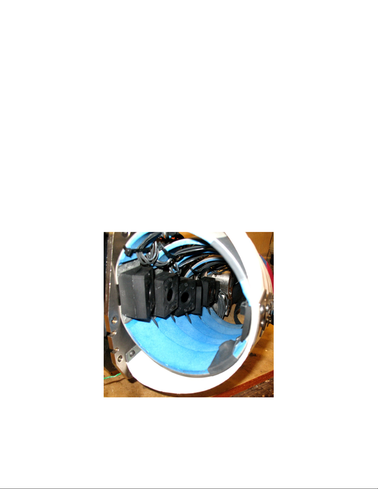
1 RibEye sensors mo nted in the d mmy ..................................................................... 5
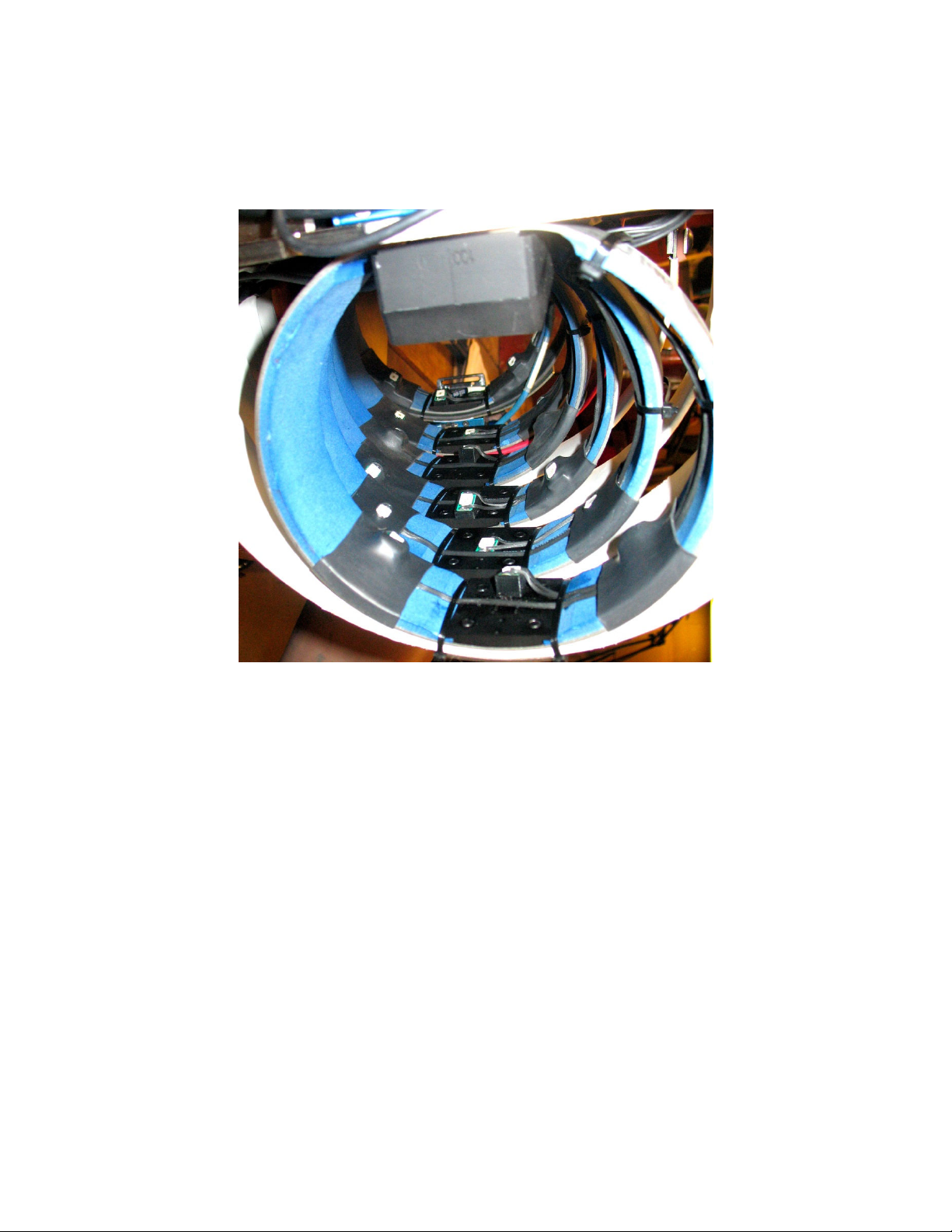
2 RibEye LEDs mo nted in the d mmy........................................................................ 6
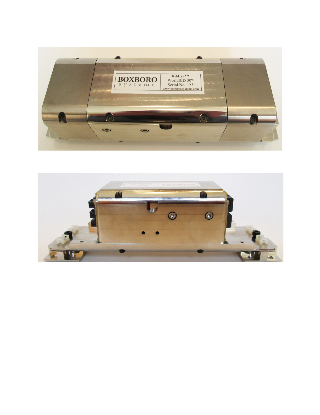
3 RibEye controller with connector covers in place ...................................................... 7
4 RibEye controller with connector covers removed .................................................... 7
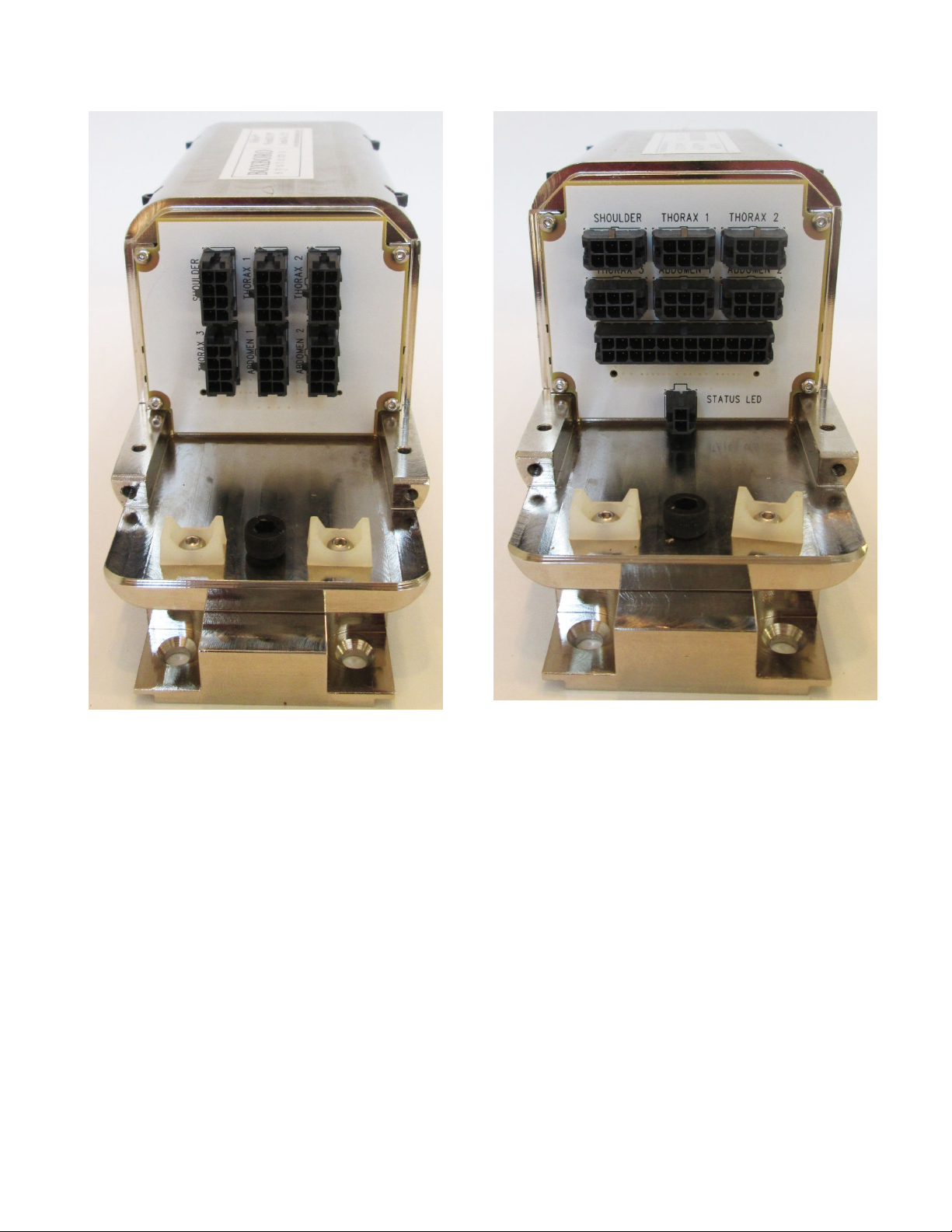
5 Controller sensor connectors ...................................................................................... 8
6 Controller connectors for LED cables, stat s cable, and d mmy exit cable .............. 8
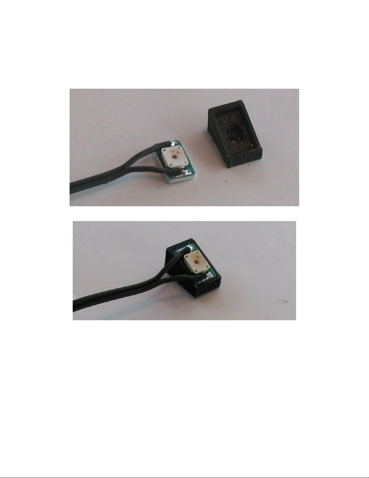
7 LED and angled mo nting block ............................................................................... 10
8 LED snapped into angled mo nting block ................................................................ 10
9 Sho lder center LED adaptor plate, inner rib clamp, and foam stopper plate ........... 11
10 Sho lder center LED assembly photo ....................................................................... 12
11 Inner rib clamp plate for thoracic and abdominal ribs............................................... 13
12 Thoracic 1 and abdominal 1 inner rib clamp plate .................................................... 14
13 Thoracic 2, thoracic 3, and abdominal 2 inner rib clamp plate ................................. 14
14 Rearward and forward LED locations ....................................................................... 15
15 Rearward LED placed on do ble-stick tape .............................................................. 16
16 Heat-shrink t bing placed over rearward LED ......................................................... 17
17 Cable ro ting for rearward and center LEDs ............................................................ 18
18 M5 x 10 flat-head cap screw with precision-machined sho lder .............................. 19
19 Sensor base with label ............................................................................................... 20
20 RibEye sensor bases mo nted to spine ...................................................................... 21
21 RibEye sensor front piece .......................................................................................... 22
22 RibEye sensor label on back and alignment pins ...................................................... 22
23 RibEye sensor assemblies mo nted to spine ............................................................. 23
24 Sensor cables ro ted to back of d mmy .................................................................... 24
25 Sensor cables tied to o ter ribs near spine plate ........................................................ 24
26 Sensor cables ro ted over the top sensor and below the neck assembly ................... 25
27 Controller adaptor installed on thoracic 1 rib ............................................................ 26
28 Controller adaptor installed on abdominal 2 rib ........................................................ 26
29 Controller end cover attachment screws .................................................................... 27
30 Controller (sensor connector end) attached to adaptor at thoracic 1 rib .................... 28
31 Controller (cable connector end) attached to adaptor at abdominal 2 rib .................. 29
32 Exit cable connector in RibEye controller ................................................................. 30
33 Cable option for DTS DAS ....................................................................................... 32
34 Cable option for Kistler NXT32 DAS ....................................................................... 33
35 Cable option for generic DAS (separate exit and breako t cables) ........................... 34
36 Cable option for generic DAS (single exit/breako t cable) ...................................... 35
37 Cable option for Kyowa DAS ................................................................................... 36
38 Cable option for Kistler KiH b/KiDa DAS ............................................................ 37
39 Sensor cables tied to controller.................................................................................. 39