Bongshin BS-235 User manual

BS-235
Digital Indicator
The Better Way for Weighing &
Measurements


1
Table of Contents
1. Introduction.....................................................................................................................................3
1-1 Trait ................................................................................................................................................... 3
1-2 Warning ............................................................................................................................................. 4
2. Specification......................................................................................................................................5
3. External Size......................................................................................................................................6
4. Description on Front Panel…...........................................................................................................7
5. Description on Rear Panel................................................................................................................9
5-1 Description on Each Terminal Unit...................................................................................................... 9
5-2 How to Use Terminal Block and Replace Fuse...................................................................................12
6. Calibration………………………............................................................................................................13
6-1 Calibration Mode …………………………........................................................................................... 13
6-2 Digital Calibration Mode..................................................................................................................... 14
6-3 Actual Load Calibration Mode............................................................................................................ 16
6-4 Linearization Calibration Mode .......................................................................................................... 18
6-5 Digital Zero Calibration Mode ............................................................................................................ 21
7. Function Mode.................................................................................................................................24
7-1 Function Setting Method.................................................................................................................... 24
7-2 Function Items ………………............................................................................................................... 25
8. HOLD ………....................................................................................................................................30
8-1 Hold Mode......................................................................................................................................... 30
8-2 Hold Type .......................................................................................................................................... 32
8-3 Hold Operation .................................................................................................................................. 33
9. Relay Mode .....................................................................................................................................35
9-1 Relay Mode ..................................................................................................................................... 35
9-2 Relay Comparator Mode................................................................................................................... 37

2
10. Analog Output...............................................................................................................................44
10-1 Analog Output Mode ...................................................................................................................... 44
10-2 Analog Output Specification and Connection Method..................................................................... 45
10-3 Analog Output Zero and Span Calibration...................................................................................... 46
10-4 Analog Output Zero and Span Minute Calibration........................................................................... 48
10-5 Analog Output Check...................................................................................................................... 50
11. Serial Output....................................................................................................................................51
11-1 RS-232C/422/485 Serial Interface ....................................................................................................... 51
11-2 Format ……….................................................................................................................................. 53
12. Check Mode ....................................................................................................................................61
12-1 Operation for Each Check Mode............................................................................................................ 61
13. Key Lock Mode ...............................................................................................................................64
13-1 Key Lock Method ............................................................................................................................... 64
13-2 Key Lock Cancellation Method ............................................................................................................. 64
14. Repair .............................................................................................................................................65
14-1 Error Message .................................................................................................................................. 65
14-2 Load Cell Inspection ........................................................................................................................... 65
14-3 Load Cell Access Diagnosis................................................................................................................. 66
14-4 Pattern of Display Letters ..................................................................................................................... 66
15. Warranty and A/S ............................................................................................................................67

3
1. Introduction
Thank you very much for purchasing this product.
This product is a model adequate for weighing and measurement system.
This equipment is a product equipped with abundant function and various external interface functions to
accommodate diverse wants of user and user can easily use this product with easy handling.
All functions can sufficiently be utilized if you thoroughly read the manual before use.
1-1 Features
BS-235 is high precision high speed indicator of 48x96mm size.
■ High precision 24bit Sigma-Delta A/D converter
■ High speed A/D and D/A conversion of 2000 time/sec
■ A/D external resolution 1/30,000
■ Actual load or digital calibration
■ Linearity Compensation Function (4 point excluding zero)
■ Low, OK, and High relay contact output
■ Hold or Peak-hold function
■ Serial Output insulation (option 1, 2, 3 - RS-232C & RS-422/485)
■ Change in relay setting value is available through communication (max. 16 ID)
■ Sensor output check function (failure inspection)
■ Analog output insulation (option 4, 5)
■ Power Source (AC 85~240V or DC 10~30V)

4
1-2 Warning
■ Check whether or not there was damage in product during the delivery.
■ Do not drop or exert server impact on the product.
■ Front panel control button is operated with light touch thus do not exert excessive strength.
■ Do not use or store product at location with severe temperature change if possible. (-10°C ~ +50°C)
■ Do not install the product at location with severe electric noise and vibration.
■ Turn off the power switch before connecting peripherals.
■ Grounding of equipment shall be conducted in order to prevent electric noise and fall.
■ Exertion of voltage or current over maximum allowable value will lead to damage in the product.
■ Power voltage shall be set within allowable range.
Use outside allowable range may cause fire, electric shock, and defect.
■ Please understand the fact that contents of manual may be changed without in advance notice.
■ Please directly contact the agency or our company regarding the inquiries to the contents of manual.
■ Please store the manual at location where it can be seen at any time after reading the manual.

5
2. Specification
Load Cell excitation DC 5V, 60mA ( 350Ω x 4 load cells can be connected )
Min. Input Sensitivity 0.2μV /Digit (min.)
Non-linearity 0.01% F.S. max.
Analog Input Signal Range -34 mV ~ +34 mV
Temperature drift Zero: ±0.1μV/°C RTI max.
SPAN: 10ppm/°C max.
Input Noise ±0.3μVpp or less
Input Impedance 10MΩ or more
A/D Internal Resolution 24 bits
Max. Display Resolution 1/30,000
A/D Sampling Speed 2,000 times/sec
Display 7-Segment red LED, 6-Digits 14.1mm high 6digit
Range of Max. Display (-)199999 ~ (+)999999
Display Conversion Speed 1,000 times/sec ~ 1 time/sec
Polarity indication (-) “-“ minus sign
Annunciators LO, OK, HI, HOLD, ZERO, STABLE
Display increments 1, 2, 5, 10, 20, 50 selectable
Decimal Point Location 0, 0.0, 0.00, 0.000, 0.0000 (selectable to any points)
Power Source AC 85~240V, 50/60Hz (Free Voltage) or DC 10~30V
Power Consumption Approx. 20VA
Range of Use Temperature -10°C ~ +50°C
Basic Output 0) Relay 3CH Output
Option Output
1) RS-232C Isolated Serial Output
2) RS-422 Isolated Serial Output
3) RS-485 Isolated Serial Output
(Conversion into RS-422/485 is available by user)
4) DC 0 ~ ±10V Isolated Analog Output
(Conversion into DC 0 ~ ±5V is available by user)
5) 4 ~ 20mA Isolated Analog Output
(Conversion into DC 0 ~ 20mA is available by user)
Product Weight About 410 g
6
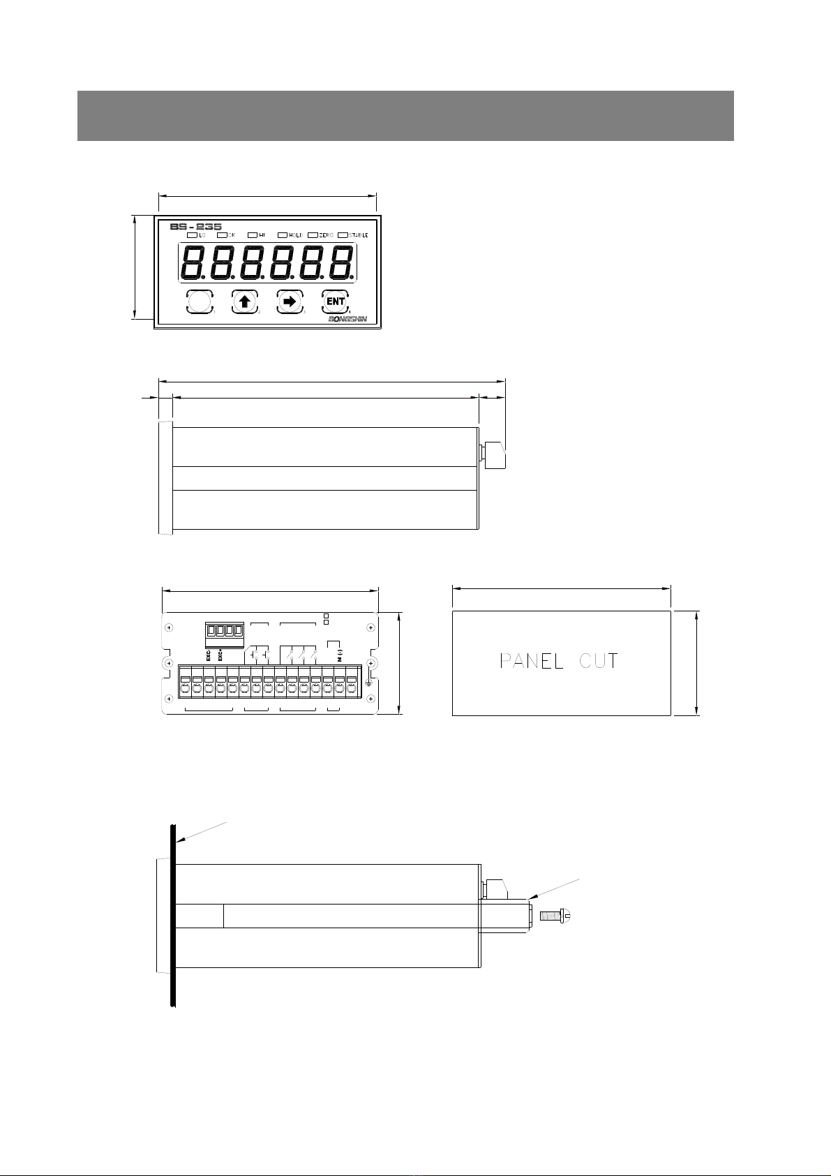
6119 11
136
48
91
43
96
92
44
OPTION
1234
SIG+
SIG-
SHD
413265 7 8 9 10 11 12 13 14 15
ZERO
COM1
INPUT RELAY OUTPUT
(L1)LO
HOLD
COM2
HI
OK
(L3)
(L2)
POWER
F.G
GND
High Precision DIGITAL INDICATOR
M
L (+)
AC 85~240V
DC 10~30V
PANEL
GUIDE
3. External Size

7
4. Description on Front Panel
STABLELO HI HOLDOK ZERO
M
High Precision DIGITAL INDICATOR
Weight Value Display
Key Switch
Status Lamp
Weight Value Display Display of measurement data and setting value is conducted.
Setting of decimal point is conducted at function mode.
Status Lamp
LO : It flickers when it is lower or higher than rLY1(L1) relay setting value.
It flickers when low value ≤ measurement value ≤ max value.
OK : It flickers when it is lower or higher than rLY2(L2) relay setting value.
It flickers when low value ≤ measurement value ≤ max value.
HI : It flickers when it is lower or higher than rLY3(L3) relay setting value.
It flickers when low value ≤ measurement value ≤ max value.
HOLD : It flickers when hold is conducted.
ZERO : It flickers when measurement value is 0 (zero).
STABLE : It flickers when measurement value is stable.
Peak HOLD : Turns on when the hold function is started.
Edge HOLD : Turns on when the value is being held.

8
M
M
M
M
Key Switch
It is used when entering user setting mode from measurement mode.
It is used when exiting to measurement mode from user setting mode.
(ESC function)
It is used as a key to increase and decrease the numerical value of selected
number line of user setting mode.
It is used as calibration mode entry key
It is used as check mode entry key
It is used as location shift key when entering numerical value of user setting mode.
It is used as calibration mode entry key
It is used as check mode entry key
It is used when shifting to next menu from user setting mode.
It is used to save or exit after entering various setting values.
It is used as calibration mode entry key.
ZERO Setting
+
It is used for zero setting.
(No.2 key while pushing No.4 key or No,.4 key while pushing No.2 key)
Function Mode
+
It is used when entering function mode.
(No. 2 key while pushing No.1 key or No.1 key while pushing No. 2 key)
Calibration Mode
+
It is used when entering calibration mode.
(No.3 key while pushing No.,2 key or No,.2 key while pushing No.,3 key)
Relay Setting
+
It is used when entering relay setting mode.
(No.3 key while pushing No.1 key or No.1 key while pushing No.3 key)
Hold Mode
+
It is used when entering hold mode.
Hold is cancelled when pushing this key once again.
(No.1 key while pushing No.4 key or No.4 key while pushing No.1 key)
Key Lock or Unlock
+
It is used for key Lock or unlock.
Lock/ unlock is repeated ever time you push this key.
(No.3 key while pushing No.4 key or No.4 key while pushing No.3 key)
Check Mode
Power OFF
+
Power ON
It is used when entering check mode.
Turn the power on when pushing two keys at once after turning off the power
(No.2 key and No.3 key at once)
※ Itdoesnotmatterwhetheryoupushonekeybeforeanotherortwokeysatonceincaseofmodetoenterby
pushingtwokeys.
Table of contents
Other Bongshin Measuring Instrument manuals


