BOCI BLT461 User manual

BLT461 Product Manual
BOCI

BLT461 Product Manual
Document History
Number Date Version
01 2022/08/19 V1.1
Notice:
Thank you for choosing the BLT intelligent cutting head. This manual provides you with
important information such as product parameters, installation, and maintenance, so
please read this manual carefully before using the product. At the same time, in order to
ensure the safety of operation and the operation of the product in the best condition,
please strictly follow the precautions in the manual.
BOCI is constantly updating/upgrading products, so our company reserves the right to
modify the product models and descriptions in this manual without prior declaration.
Unauthorized disassembly of the product is strictly prohibited without the
authorization of BOCI Technology, otherwise the warranty will be invalid!
BOCI

BLT461 Product Manual
Table of contents
BLT461 Product Manual ...........................................................................1
1. Product Description ............................................................................. 1
1.1 Product View .................................................................................................................................................... 1
1.2 Technical parameters ......................................................................................................................................2
1.3 Meaning of LED indicator ................................................................................................................................ 3
2. Gas port ...............................................................................................4
3. Water cooling interface ....................................................................... 5
4. Electrical interface ...............................................................................6
4.1 Bus system ....................................................................................................................................................... 7
4.2 Non-bus systems ............................................................................................................................................. 8
5. Cutting head installation ..................................................................... 9
5.1 Preparation before operation ......................................................................................................................... 9
5.2 Specific operation process ............................................................................................................................ 10
5.2.1 Preparation of clean bench .................................................................................................................10
5.2.2 The cutting head is placed in the clean workbench ........................................................................... 10
5.2.3 Clean and wipe the fiber interface of the cutting head ......................................................................11
5.2.4 Check the laser fiber end face .............................................................................................................11
5.2.5 Tear off the protective film/remove the protective cap ..................................................................... 11
5.2.6 Insert the laser fiber interface into the cutting head .......................................................................... 12
5.2.7 Wrap and seal ......................................................................................................................................12
5.2.8 Mount the cutting head on the backplane ..........................................................................................13
5.2.9 Installing the ceramic body and nozzle ..............................................................................................14
BOCI

BLT461 Product Manual
5.2.10 Beam centering ..................................................................................................................................15
Appendix A - Care/Maintenance ........................................................... 17
1.1 Schematic diagram of product structure ...................................................................................................... 17
1.2 Replace the upper protective lens ................................................................................................................ 18
1.3 Replace the lower protective lens .................................................................................................................19
Appendix B - Mechanical Dimensions ................................................... 20
1.1 Cutting head installation size ........................................................................................................................20
BOCI
BLT461 Product Manual
1
1. Product Description
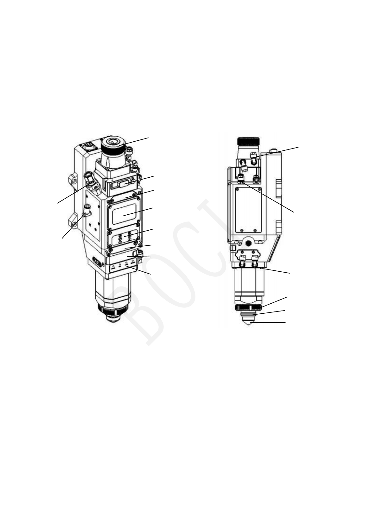
1.1 Product View
Product View (Structure and Interface Description)
1. Optical fiber interface; 9. Nozzle cooling air interface;
2. 1st Upper protective lens; 10. Cutting gas interface;
3. 2nd Upper protective lens; 11. Cooling water outlet;
4. Collimation unit; 12. Cooling water inlet;
5. Focusing unit; 13. Anti-collision screw;
6. 2nd Lower protective lens; 14. Ceramic body lock ring;
7. 1st Lower protective lens; 15. Ceramic body;
8. Working indicator; 16. Nozzle;
1
2
10
3
4
5
6
9
12
11
8
14
15
16
13
14
7
BOCI

BLT461 Product Manual
2
1.2 Technical parameters
Cutting head BLT461
Laser wavelength: 1030-1090nm
Laser power: ≤20kW
Fiber interface: Q+、QD、QBH、ADD
Spot magnification: M=1.5/2.0 (100:150/100:200)
Focus adjustment range: ±50mm (optical ratio 1:2 100:200)
NA: Max.0.13 at Fc100
Centering adjustment range: ±1.5mm
Focus acceleration: 7.5m/s²
Cutting gas interface: ø10, maximum 25bar (2.5Mpa)
Nozzle cooling gas connection: ø6, maximum 5bar (0.5Mpa)
Water cooling interface: ø8, maximum 5bar (0.5Mpa), minimum flow 2.0l/min
Operating temperature: 5~55℃
storage temperature: -25~+55 ℃
size: 404x122
weight: About 5.5kg
Notice:
To avoid damage to the cutting head during storage and transportation, pay attention to
the following:
The cutting head should be stored within the allowable temperature and humidity
range.
Avoid storage in and near magnetic fields such as permanent magnets or strong
alternating fields.
Avoid collision of the cutting head.
BOCI
BLT461 Product Manual
3
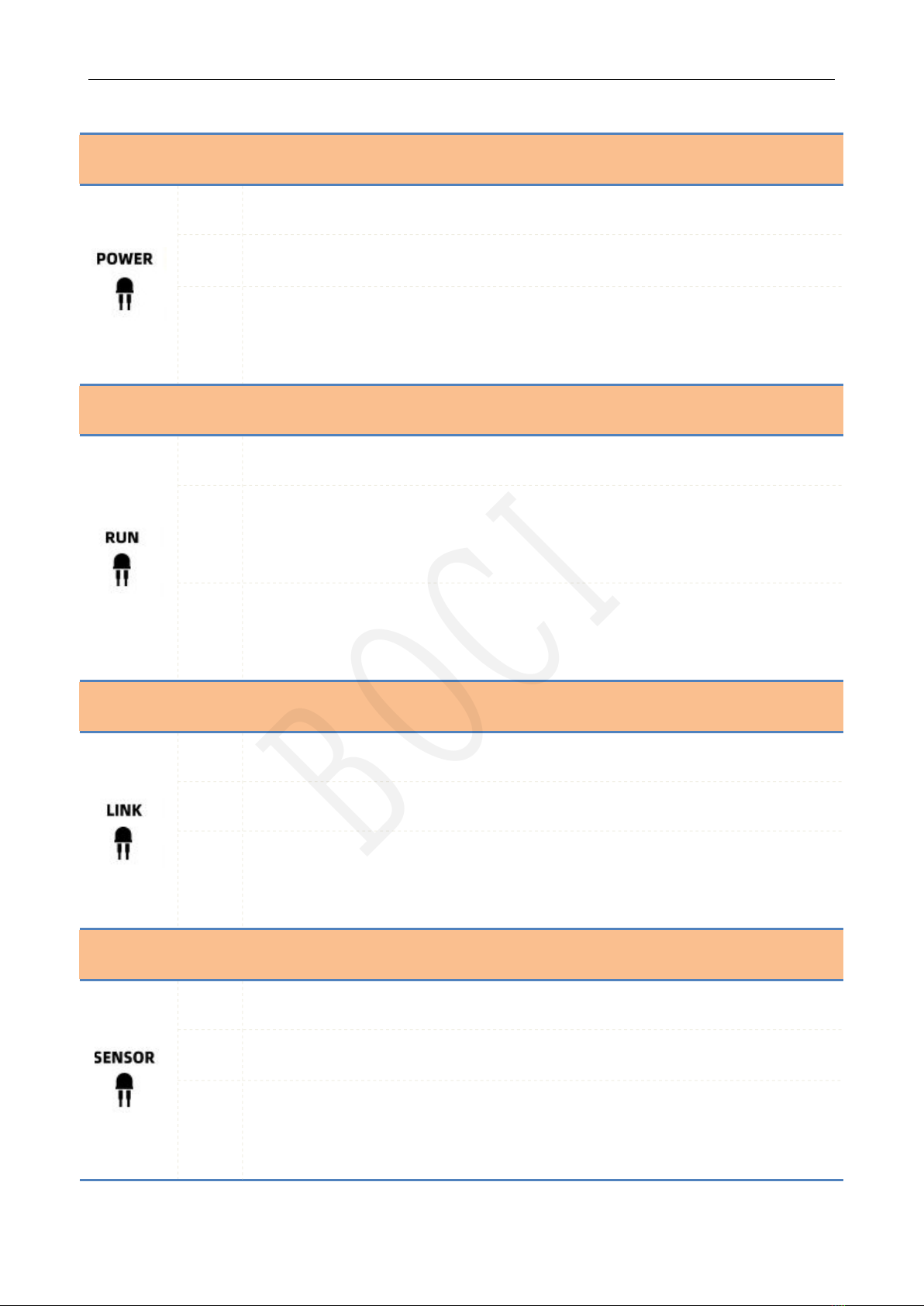
1.3 Meaning of LED indicator
icon state meaning
green Power is normal.
red Under-voltage alarm: insufficient electrical power.
not
bright
No power supply: There is no power supply, the connection cable is broken, and the
interface is loose.
icon state meaning
green The system is operating normally.
red
Abnormal motor: The current consumption of the motor is too large, and the
mechanical components cannot run smoothly.
not
bright
The cable is broken, and the interface is loose.
icon state meaning
green System communication is normal.
red System communication is abnormal.
not
bright
The cable is broken, and the interface is loose.
icon state meaning
green The readings of each sensor are normal.
red There is an abnormal sensor reading.
not
bright
The cable is broken, and the interface is loose.
BOCI

BLT461 Product Manual
4
2. Gas interface
Installation connection: cutting gas 1, nozzle cooling gas 2
Notice:
The maximum pressure of cutting gas is 25bar (2.5Mpa).
The cutting gas quality shall meet the requirements of gas quality in accordance with ISO
8573-1:2010: solid particles - class 2, water - class 4, oil - class 3. The purer the cutting gas,
the longer the life of the protective lens.
The cutting gas pipe diameter (outer diameter) is 10mm, and the nozzle cooling gas pipe
diameter (outer diameter) is 8mm.
Cutting gas
interface
Nozzle cooling gas
connection
BOCI

BLT461 Product Manual
5
3. Water cooling interface
Installation connection: water-cooled water inlet port 2A, water-cooled water outlet port 1A
Notice:
Deionized/distilled water (conductivity < 10 μ S/cm) specified by the laser manufacturer is
recommended.
Recommended cooling water setting value: cooling water pressure ≤5bar (0.5Mpa), water flow rate ≥
2.0l/min.
Please refer to the dew point table to set the cooling water temperature to prevent condensation on
the optical components.
Dew point temperature at different temperature and humidity
Water cooling water
outlet
Water
cooling
water
BOCI

BLT461 Product Manual
6
4. Electrical Interface
PWE and aviation plug interface waterproof precautions:
1. PWE interface and air plug interface are equipped with dust plugs from the
factory. If the dust plug does not fall off, the protection level of IP64 can be
achieved; at the same time, when the PWE cable and the air plug cable are
well connected, IP64 can also be achieved;
2. After the dust plug is removed, the protection level of IP64 cannot be achieved.
If it encounters spraying or flushing at this time, it will cause water to enter the
product and affect the function;
3. Ensure that the water circuit is connected well, and the water pipe interface is
tightened before removing the dust plug to prevent the water pipe from
accidentally loosening and water rushing to the interface, causing the product
to enter the water;
4. When adjusting the wiring, remove the dust plug for wiring. It is recommended
to keep the removed dust plug of the PWE interface. Install the dust-proof plug
as soon as possible after the stitches are removed to prevent accidental water
ingress in the transfer, water connection and other links.
BOCI
Table of contents
Other BOCI Industrial Equipment manuals