Belden PPC CABLEREADY SR050 Datasheet

CABLEREADY®
Installation Instruction Guide

This product may be protected by one or more patents • For further information, please visit: www.ppc-online.com/patents
6176 E. Molloy Rd. East Syracuse, NY 13057 U.S.A. • [email protected] • 1-800-800-6652 • +1 315-431-7200 • www.ppc-online.com
CABLEREADY®
Installation Instruction Guide
3
4
5
6
7
8
9
10
11
11
15
16
17
18-19
Table of Contents
1.0 Introduction
2.0 Tools
3.0 General Instructions
4.0 Clip Installation
4.1 Anchors
4.2 Tie Wrap Guides
5.0 Straight Run Molding Installation
6.0 Fittings
7.0 Special Instructions
7.1 Molding Bridge Instructions
7.2 Interior Instructions
8.0 How To Re-Enter Straight Run Molding
9.0 Helpful Hint
Easy Re-Order Guide
2

This product may be protected by one or more patents • For further information, please visit: www.ppc-online.com/patents
6176 E. Molloy Rd. East Syracuse, NY 13057 U.S.A. • [email protected] • 1-800-800-6652 • +1 315-431-7200 • www.ppc-online.com
CABLEREADY®
Installation Instruction Guide
1.0 INTRODUCTION
CABLEREADY offers a series of protective molding developed to meet the needs of an ever-changing
cable industry.
In response to industry demands and with many years of multi-unit construction experience,
CABLEREADY designers were able to develop a protective molding raceway that not only meets
but exceeds the cable industry’s standards. This protective raceway molding simplies the installation
process as well as, provides a highly secure system to keep
vandals out of the system.
CABLEREADY has since been an industry leader in developing the most innovative solutions to the
challenges that installers must face when working with cable molding. CABLEREADY molding and
ttings are available in ve different colors. Fittings are offered as transitions between sizes, right
angles, Tee Fittings and much more.
Our molding is made of 26 gauge Galvalume® steel. Galvalume® lasts longer and is far more durable
than G90 hot dipped steel or plastic
molding systems.
In the past, system operators, installers and apartment owners have settled for plastic moldings that
were difcult to install, re-enter and
re-install with an effective product life of only two to three years. Users have had to put up with plastic
moldings that would crack, shift, discolor, warp and literally falloff the walls of buildings.
Our CABLEREADY molding is guaranteed against cracking, warping, discoloring, blistering or peeling
due to ultraviolet rays or harsh weather conditions for 15 years. All CABLEREADY molding products
can be used for indoor and outdoor applications.
Please read these instructions thoroughly prior to installing CABLEREADY molding to ensure proper
installation of CABLEREADY products and to ensure ease of upgrade or repair to the system. If you
need additional assistance or simply have questions about CABLEREADY products, please contact
3

This product may be protected by one or more patents • For further information, please visit: www.ppc-online.com/patents
6176 E. Molloy Rd. East Syracuse, NY 13057 U.S.A. • [email protected] • 1-800-800-6652 • +1 315-431-7200 • www.ppc-online.com
CABLEREADY®
Installation Instruction Guide
2.0 TOOLS
Recommended Tools: The following tools and materials are recommended to ensure a safe and correct
installation of CABLEREADY’s protective molding system.
• GLOVES: CABLEREADY’s protective molding is manufactured with 26 gauge Galvalume® steel.
The molding, clips, and ttings may have sharp edges on the material. USE GLOVES AT ALL
TIMES.
• HAND CUTTERS (HC1251 OR HC1451): The HC1251 hand cutter are used to cut straight run to
desired lengths. The HC1451 super snip hand cutters are used to make specialty cuts and notches
in the straight run. Note: Do not use sheet metal shears. Sheet metal shears leaves uneven edges
on the straight run molding.
• CORDLESS HAMMER DRILL: Use a battery charged portable hammer drill for best results.
• ANCHORS: CABLEREADY offers a full line of anchors, nylon anchor, wall grabbers, #8 Hex Head
screws and much more. See Section 4.1 for recommended anchors. Note: Anchor types and sizes
will vary depending on the surface you are working on.
• CHALKLINE: Extend the chalk line string and tie 5cm long string every 10cm to mark any surface
for correct clip layout.
• TAPE MEASURE: If you do not adjust your chalk line to snap a mark every 10cm, use a tape
measure to set up center points on the chalk line for placement clips.
• ENTRY KEYS: CABLEREADY molding is designed to be removed from the clip or full backing
clip with our patented entry key. The EK050HD is used to re-enter SR050 (11mm molding) only.
The EK100HD is used to re-enter SR075, SR100, and SR200 straight run molding
4

This product may be protected by one or more patents • For further information, please visit: www.ppc-online.com/patents
6176 E. Molloy Rd. East Syracuse, NY 13057 U.S.A. • [email protected] • 1-800-800-6652 • +1 315-431-7200 • www.ppc-online.com
CABLEREADY®
Installation Instruction Guide
3.0 GENERAL INSTRUCTIONS
General Instructions: When installing CABLEREADY’s molding, try to follow window trims,
drain pipes, rain gutters, and other natural edges on the building. Make certain that all of your
measurements allow for adequate space (at least one inch) between existing edge and the molding.
• First, plan the lay out of the molding.
Be sure to plan for bend radius and obstacles.
Some building surfaces require specic types of anchors. (Section 4.1)
Certain building surfaces require special preparation (i.e.Stucco Walls 7.2).
Design the molding to run the full length of the building.
• Run chalk line.
You can modify your chalk line by tying knots in the line.
Tie a knot every 1.2m. This will indicate where the clips need to be placed.
Snap chalk line 5cm away from any edging. (Figure 1) Note: If CABLEREADY molding is in
stalled too close to the edging, it may cause re-entering the system to be difcult.
DO NOT run your chalk line too long. This will cause your line to sag in the middle and you
will not have a straight line!
OR
Cut a length of straight run molding in half (1.2m) and use length as a template.
• Install Clips. (Section 4.0)
• Install Straight Run Molding. (Section 5.0)
5cm
Chalkline
5

This product may be protected by one or more patents • For further information, please visit: www.ppc-online.com/patents
6176 E. Molloy Rd. East Syracuse, NY 13057 U.S.A. • [email protected] • 1-800-800-6652 • +1 315-431-7200 • www.ppc-online.com
CABLEREADY®
Installation Instruction Guide
4.0 CLIP INSTALLATION
An easy formula for determining the number of clips needed is to multiply the footage of straight run
by .25 for each size ordered.
Example: 4000’ of SR100IV x .25 = 1000 CL100
• Only 2 clips are needed per 2.4m section of CABLEREADY molding.
• Use the full backing clip for uneven surfaces or when a highly secured system is required. Use the
full backing clip only where the molding is accessible, for instance, the rst 2.4 to 4.8m.
• For Stucco surfaces we recommend using the full backing plate.
• Line up clip to the chalk line and mark surface to where the holes will be drilled. Align the clips’ end
guides with the chalk line. (Figure 2)
• Drill (2) 5mm holes. (Figure 3)
• Use 2 anchors per clip. (Figure 4) (Section 4.1)
• Starting from the ground up, the rst clip should be ush with the end of the molding edge.
Note: This is the only time the clip will be ush with the molding edge. Measurement from the center
of this clip to thecenter of the next clip will be 1.15m”.
• After these rst and second clips are placed, space subsequent clips at 1.2m from center clip to
center clip (Figure 5), except when measuring for ttings. (Section 6.0)
• Insert tie wrap before mounting clip to your surface.
• Once the clips have been installed, use a tie wrap to secure cables to the clip. (Section 4.2)
• Note: The clip acts as an attachment mechanism between two pieces of straight run molding
(Figure 6). (i.e. when you install clips only half of the clip will be covered by molding. The other half
of the clip will serve as the beginning attachment for the next piece of molding clips.
Figure 2. Figure 3. Figure 4.
1.2m
Center Clip
Center Clip
Figure 5.
Figure 6.
6

This product may be protected by one or more patents • For further information, please visit: www.ppc-online.com/patents
6176 E. Molloy Rd. East Syracuse, NY 13057 U.S.A. • [email protected] • 1-800-800-6652 • +1 315-431-7200 • www.ppc-online.com
CABLEREADY®
Installation Instruction Guide
4.1 ANCHORS
• Use 2 anchors per clip. Note: clips can be cut in 1/2, only use 1 anchor.
• Anchors slightly smaller than the holes drilled should be used to hold clips (5mm recommended).
(Figure 3)
• The following anchors are recommended for each particular application:
Wood Siding: #8 or #10 x 1” Hex Head Screw (use with drill).
Brick, Concrete, Cinder Block, Stone or Stucco: 5mm x 25mm or 5mm x 38mm Nylon
Nail-In Anchors (use with hammer) or Plastic Anchors with Hex End Screws (use with drill).
Drywall or Plaster: Wallgrabbers® (no drilling is required) Use hammer to drive in
Wallgrabbers® and insert #8 Hex Head Screw.
• When using a hammer to insert anchors for securing clips, be careful not to hammer the side of the
clips. Bending the clips will cause removal of molding difcult. Note: For the CL050 (1.1cm clip) we
recommend our anchor driver (CR-7TD).
• Continue to check for alignment of the clip and guides with the chalk line before nally securing the
anchor into place.
• Normally anchors are installed in the holes horizontally. If the surface is slightly uneven, install
anchors in the vertical holes.
Example:
7

This product may be protected by one or more patents • For further information, please visit: www.ppc-online.com/patents
6176 E. Molloy Rd. East Syracuse, NY 13057 U.S.A. • [email protected] • 1-800-800-6652 • +1 315-431-7200 • www.ppc-online.com
CABLEREADY®
Installation Instruction Guide
4.2 TIE WRAP GUIDES
• Once the clips have been installed, use one tie wrap to secure cables
to the clip. (Figure 7)
• The tie wrap should be threaded through the tie wrap guides.
• Pull tight around cables so that molding can snap on without pinching
the cable.
• Try to maintain symmetry in batching cables to assure ease of tracking
cables over long distances.
• Use a tie wrap in between clips to help align cables within the molding.
Figure 7.
8

This product may be protected by one or more patents • For further information, please visit: www.ppc-online.com/patents
6176 E. Molloy Rd. East Syracuse, NY 13057 U.S.A. • [email protected] • 1-800-800-6652 • +1 315-431-7200 • www.ppc-online.com
CABLEREADY®
Installation Instruction Guide
5.0 STRAIGHT RUN MOLDING INSTALLATION
• Keep protective lm on the molding until the molding is installed.
• Place one edge of the straight run under one edge of the clip. Apply pressure to the at top of the
molding, and push the molding down while pulling the molding’s ange out toward the unsecured
edge of the clip. (Figure 8)
• When snapping the molding on, start from one end and work toward the other. Never start from the
middle and then work to the outside.
• When installing vertical risers, it is recommended that all short pieces be placed at the top riser.
• The vertical riser needs to rest on something that will support the molding. (i.e. trim board, cement,
or a screw) If not unsupported the riser will slide down over a period of time and will cause a gap.
• A slight space (about 5mm) should be left between each section of molding. This allows the molding
to move with the natural expansion and contraction.
• Install a coupling at each joint of molding. This will cover any spaces between sections.
• Short pieces will require a clip on each end.
• If molding seams loose on clip slightly squeeze the molding.
Figure 8.
9
This product may be protected by one or more patents • For further information, please visit: www.ppc-online.com/patents
6176 E. Molloy Rd. East Syracuse, NY 13057 U.S.A. • [email protected] • 1-800-800-6652 • +1 315-431-7200 • www.ppc-online.com
CABLEREADY®
Installation Instruction Guide
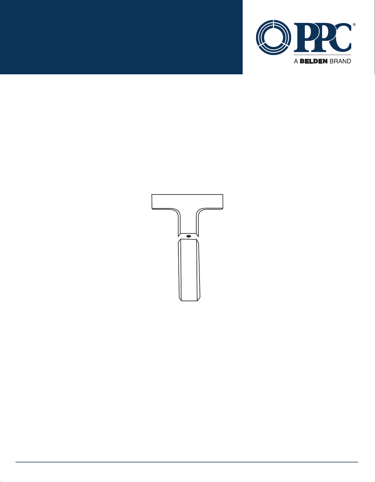
6.0 FITTINGS
• Unlike the straight run molding, the ttings should have the protective lm removed before
installation.
• When using ttings, place the clip closest to the tting approximately 50mm from the end of the
straight run.
• The majority of the 1.9cm, 2.5cm, and 5.1cm ttings are snap on ttings. The snap on ttings are
easy to identify because they have a set of tabs on the bottom of the tting.
• The other ttings are inserted into the end of piece of molding, and will have notches on each side
where the molding ts. (Figure 9)
• All 1.1cm ttings snap directly onto a CL050 clip. None of the ttings snap over or into the molding.
• The CO200, the 5.1cm coupling needs to be installed at the same time as the molding. The
interlocking bracket must t securely between the two lengths of straight run.
• When using the CT075 as a tee tting, you do not want the two molding ends to share a clip. You
need a 25mm space between the two ends. This allows room to make the TEE.
• Note: All ttings are designed to meet bend radius at full cable capacity.
Figure 9.
10
This manual suits for next models
3
Table of contents
Other Belden Industrial Equipment manuals


