8
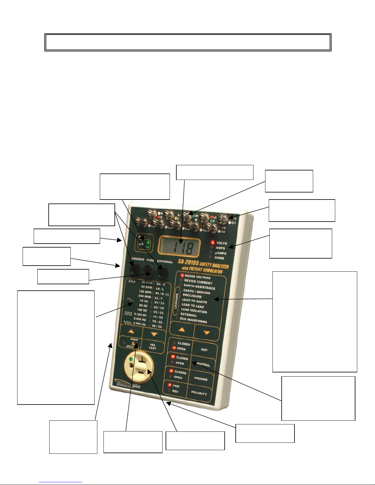
Analyzer Test Receptacle Control
There are four keys and 8 LEDs in the Analyzer Test Receptacle Control Section. They
allow the manual control of the power connections that are made to the DUT. Internally, a
series of relays are switched by the microprocessor based on the keys that are depressed.
The LEDs indicate the current state of the power connections to the Receptacle.
Note: The Forward/Reverse keys have an internal switching delay feature that first turns off
the power to the DUT, delays for a short period, reverses the lines and the turns the unit
back on. This eliminates the need for the user to remember to delay at this point or risk
damage to the Analyzer.
Patient Lead Control
In the maximum configuration, there are ten patient lead inputs. During testing, it is
necessary to select between these leads, select all of them and apply High Voltage to
them. This section provides the control keys to do these test configurations and the LEDs
to indicate the current state.
There is one LED for each input. The markings on the right side of the LEDs are used
during these tests. Internally, there is a relay for each lead. The LEDs indicate when that
relay is on, thus selecting the indicated lead. The Up and Down arrow keys sequentially
select each lead in order and scroll through from None to 1-10 to All and around again.
To apply High Voltage to the leads, the Isolation Test key is depressed. It is only active in
the Isolation mode. It is a momentary key, the voltage is only applied while the key is held
down.
Waveform Selection
When the ECG Waveforms function is selected, the two keys and 10 LEDs become the
Waveform Selection Control Section. The markings o the left side of the LEDS are used
during these tests. The LEDs indicate which waveform is generated. The Up and Down
arrow keys sequentially select each waveform. Internally, the microprocessor has stored in
memory the digitalized waveforms. It sends the selected waveform to a D/A converter that
generates an accurate analog representation. This waveform is then sent through a
resistor network, developing the appropriate signals on the output terminals.
Power Outlet Indicators
These three Neon indicators help verify the polarity and wiring of the wall Receptacle that
the Safety Analyzer is plugged into.