Bühler technologies FCT User manual

Fluidcontrol
Installation and Operation Instructions
Original instructions
Fluidcontrolterminal FCT
BE100006
02/2022
Bühler Technologies GmbH, Harkortstr. 29, D-40880 Ratingen
Tel. +49 (0) 21 02 / 49 89-0, Fax: +49 (0) 21 02 / 49 89-20
E-Mail: [email protected]
Internet: www.buehler-technologies.com

Bühler Technologies GmbH, Harkortstr. 29, D-40880 Ratingen
Tel. +49 (0) 21 02 / 49 89-0, Fax: +49 (0) 21 02 / 49 89-20
Internet: www.buehler-technologies.com
E-Mail: [email protected]
Read this instruction carefully prior to installation and/or use. Pay at-
tention particularly to all advises and safety instructions to prevent in-
juries. Bühler Technologies can not be held responsible for misusing
the product or unreliable function due to unauthorised modifications.
All rights reserved. Bühler Technologies GmbH 2023
Document information
Document No......................................................... BE100006
Version.........................................................................02/2022

Fluidcontrolterminal FCT
Contents
1 Introduction.....................................................................................................................................................................................................................2
1.1 Intended Use.........................................................................................................................................................................................................2
1.2 Product Description............................................................................................................................................................................................ 2
1.3 Model Key .............................................................................................................................................................................................................. 3
1.4 Scope of Delivery..................................................................................................................................................................................................3
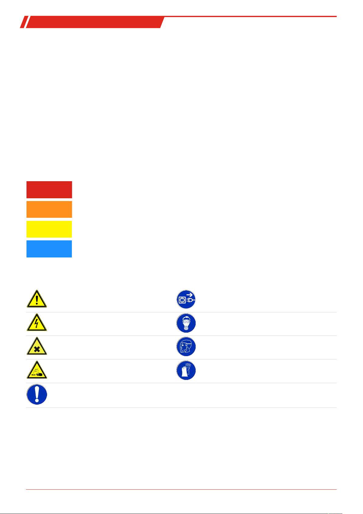
2 Safety instructions .........................................................................................................................................................................................................4
2.1 Important advice .................................................................................................................................................................................................4
2.2 General hazard warnings ................................................................................................................................................................................. 5
3 Transport and storage ..................................................................................................................................................................................................6
4 Installation and connection ........................................................................................................................................................................................ 7
4.1 Installation ............................................................................................................................................................................................................ 7
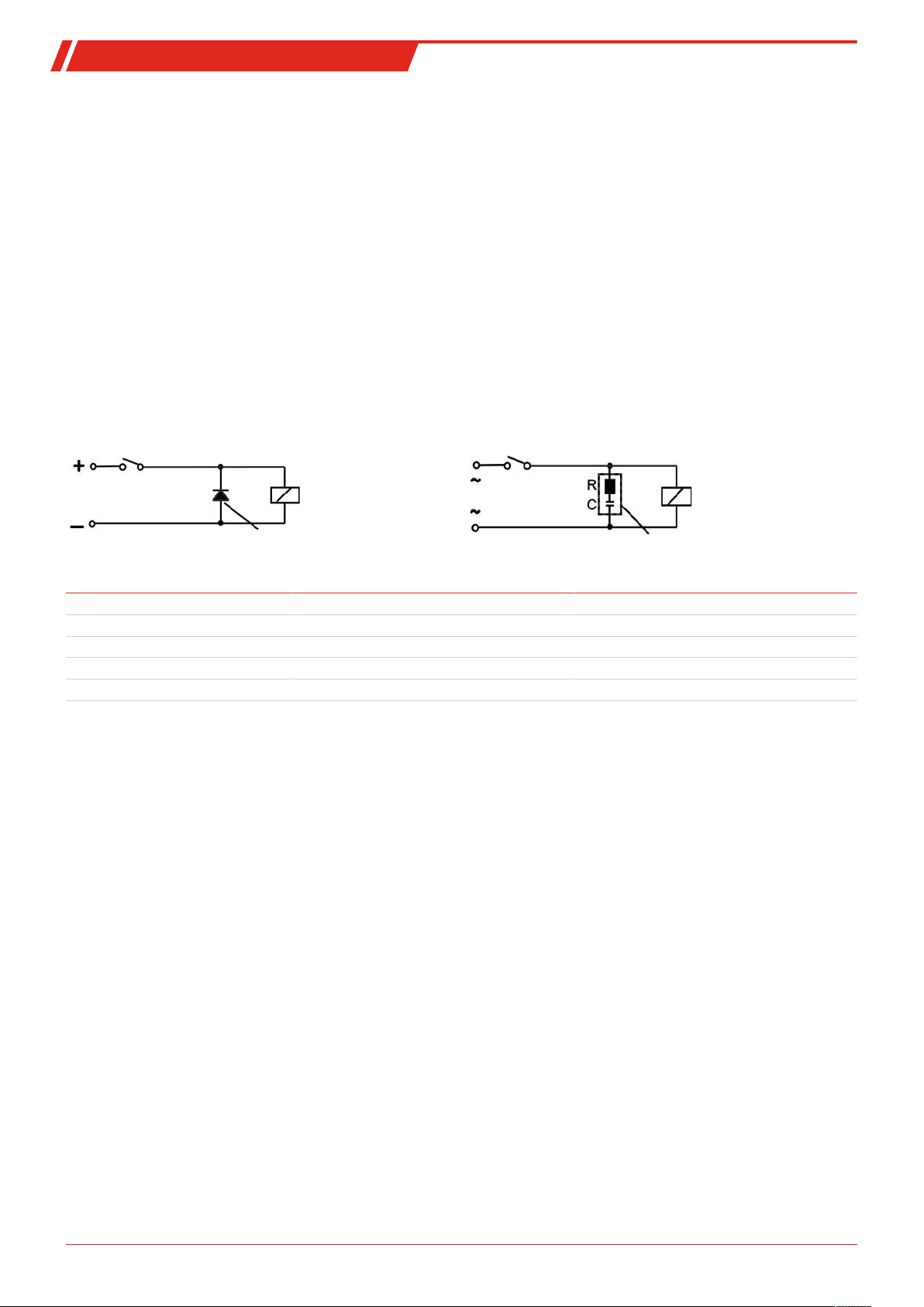
4.2 Level Switch Electrical Connections ............................................................................................................................................................... 7
4.3 Information on the correct operation of reed contacts in Bühler level switches.............................................................................8
4.4 Vacuum Switch Electrical Connection ..........................................................................................................................................................9
4.5 Sampling Port.......................................................................................................................................................................................................9
4.6 Filling Coupler Connection...............................................................................................................................................................................9
5 Operation and control ................................................................................................................................................................................................10
5.1 Level Switch.........................................................................................................................................................................................................10
5.2 Sampling..............................................................................................................................................................................................................10
5.2.1 Sampling From the Tank..................................................................................................................................................................10
5.2.2 Sampling From The Return Filter ..................................................................................................................................................10
5.3 Manual Filling .....................................................................................................................................................................................................11
6 Maintenance and repair............................................................................................................................................................................................. 12
6.1 Filter Change....................................................................................................................................................................................................... 12
7 Service and repair......................................................................................................................................................................................................... 13
8 Disposal ........................................................................................................................................................................................................................... 14
9 Appendices ......................................................................................................................................................................................................................15
9.1 Technical Data.....................................................................................................................................................................................................15
9.2 Airflow/Back Pressure Table .......................................................................................................................................................................... 16
10 Attached documents ....................................................................................................................................................................................................17
iBühler Technologies GmbHBE100006 ◦ 02/2022

Fluidcontrolterminal FCT
1 Introduction
1.1 Intended Use
The fluid control terminal is a compact adapter flange with several connection options for individual applications.
The design of the fluid control terminal allows for flexible equipment so the device can easily be adapted to the requirements of
the specific application. The required space and installation are minimal.
Please note the technical data in the appendix for the specific intended use, existing material combinations, as well as temper-
ature limits.
WARNING
All device models are solely intended for industrial applications. They are not safety com-
ponents. The devices must not be used if failure or malfunction thereof jeopardises the
safety and health of persons.
Use in explosive areas is prohibited.
1.2 Product Description
The fluid control terminal consists of a compact adapter flange with circuit diagram as per DIN24557Part 2 and offers connec-
tions for a filling coupler, a vacuum switch and a sampling port. A level- and temperature switch with vent filter is integrated.
The fluid control terminal installs directly to the tank.
If needed, different filling couplings, contamination indicators and sampling ports can be added on. The following illustration
shows the fluid control terminal with the equipment options:
Fig.1:
1 Flange with connection options 4 Filling port
2 Sampling port 4a Filling port type Walther (optional)
2a Minimess (optional) 4b Filling port type Stäubli with G3/4 to G1/2 reducer
(optional)
2b Hose coupling with sleeve (optional) 5 Port for vacuum switch (optional)
3 Level- and temperature switch with vent filter
2 Bühler Technologies GmbH BE100006 ◦ 02/2022

Fluidcontrolterminal FCT
1.3 Model Key
Length (max. 1420 mm)
280
370
500
Option 1: Sampling port
PSK
PMM
Hose coupling (DN 5)
Minimess coupling(M16)
VUS
VBS
Vacuum switch (elec.)
Dummy plug
Option 3: Vacuum switch
Type: Walther (DN 19)
Type: Stäubli (DN 11)
Dummy plug
BWA
BST
BBS
Option 2: Filling port
FCT-G3/4-
Variable (please specify)
Type designation/port
---
1.4 Scope of Delivery
– Fluid control terminal
– Product documentation
– Connection/mounting accessories (optional)
3Bühler Technologies GmbHBE100006 ◦ 02/2022

Fluidcontrolterminal FCT
2 Safety instructions
2.1 Important advice
Operation of the device is only permitted if:
– the product is used under the conditions described in the installation- and operation instruction, the intended application
according to the type plate and the intended use. In case of unauthorized modifications done by the user Bühler Technolo-
gies GmbH can not be held responsible for any damage,
– when complying with the specifications and markings on the nameplates.
– the performance limits given in the datasheets and in the installation- and operation instruction are obeyed,
– monitoring devices and safety devices are installed properly,
– service and repair is carried out by Bühler Technologies GmbH,
– only original spare parts are used.
This manual is part of the equipment. The manufacturer keeps the right to modify specifications without advanced notice. Keep
this manual for later use.
Signal words for warnings
DANGER
Signal word for an imminent danger with high risk, resulting in severe injuries or death if not avoided.
WARNING
Signal word for a hazardous situation with medium risk, possibly resulting in severe injuries or death if not
avoided.
CAUTION
Signal word for a hazardous situation with low risk, resulting in damaged to the device or the property or
minor or medium injuries if not avoided.
NOTICE
Signal word for important information to the product.
Warning signs
These instructions use the following warning signs:
Warns of a general hazard Unplug from mains
Voltage warning Wear respiratory equipment
Warns not to inhale toxic gasses Wear a safety mask
Warns of corrosive liquids Wear gloves
General information
4 Bühler Technologies GmbH BE100006 ◦ 02/2022

Fluidcontrolterminal FCT
2.2 General hazard warnings
The equipment must be installed by a professional familiar with the safety requirements and risks.
Be sure to observe the safety regulations and generally applicable rules of technology relevant for the installation site. Prevent
malfunctions and avoid personal injuries and property damage.
The operator of the system must ensure:
– Safety notices and operating instructions are available and observed,
– The respective national accident prevention regulations are observed,
– The permissible data and operational conditions are maintained,
– Safety guards are used and mandatory maintenance is performed,
– Legal regulations are observed during disposal,
– compliance with national installation regulations.
Maintenance, Repair
Please note during maintenance and repairs:
– Repairs to the unit must be performed by Bühler authorised personnel.
– Only perform conversion-, maintenance or installation work described in these operating and installation instructions.
– Always use genuine spare parts.
– Do not install damaged or defective spare part. If necessary, visually inspect prior to installation to determine any obvious
damage to the spare parts.
Always observe the applicable safety and operating regulations in the respective country of use when performing any type of
maintenance.
The method for cleaning the devices must be adapted to the IP protection class of the devices. Do not use cleaners which could
damage the device materials.
DANGER Toxic, acidic gases/liquids
Protect yourself from toxic, corrosive gasses/liquids when performing any type of work.
Wear appropriate protective equipment.
DANGER Electrical voltage
Electrocution hazard.
a) Disconnect the device from power supply.
b) Make sure that the equipment cannot be reconnected to mains unintentionally.
c) The device must be opened by trained staff only.
d) Regard correct mains voltage.
DANGER Potentially explosive atmosphere
Explosion hazard if used in hazardous areas.
The device is not suitable for operation in hazardous areas with potentially explosive at-
mospheres.
Do not expose the device to combustible or explosive gas mixtures.
5Bühler Technologies GmbHBE100006 ◦ 02/2022

Fluidcontrolterminal FCT
3 Transport and storage
Only transport the product inside the original packaging or a suitable alternative.
The equipment must be protected from moisture and heat when not in use. It must be stored in a covered, dry, dust-free room
at room temperature.
6 Bühler Technologies GmbH BE100006 ◦ 02/2022

Fluidcontrolterminal FCT
4 Installation and connection
DANGER Electric voltage
Risk of electric shock
a) Always disconnect the unit from the mains before performing work.
b) Secure the equipment from accidental restarting.
c) The equipment may only be installed, maintained and put into operation by instruc-
ted, competent personnel.
d) Always observe the applicable safety regulations for the operating site.
CAUTION Wrong mains voltage
Wrong mains voltage may damage the device.
Regard the correct mains voltage as given on the type plate.
4.1 Installation
The fluid control terminal resp. filling and vent adapter comes fully assembled and can be mounted to the tank using the in-
cluded screws and seals.
Please be sure to leave enough space between the tank wall and add-ons during installation.
The mounting hole pattern as per DIN24557Part 2 with six mounting holes allows installation rotated by 60° each. If your unit
has a filling coupler and/or Minimess coupler or hose coupling, arrange these to ensure free access to these parts at all times.
6x Ø6
Ø73
Ø90
Ø60
Installation opening
as per DIN 24557/Part 2
Fig.2: Flange
4.2 Level Switch Electrical Connections
For information on connecting the level switch, please refer to the operating instructions included with the level switch.
7Bühler Technologies GmbHBE100006 ◦ 02/2022

Fluidcontrolterminal FCT
4.3 Information on the correct operation of reed contacts in Bühler level switches
Based on their construction, reed contacts are very long lasting and reliable components. Yet the following should be considered
when using them:
Life of reed switches
The life of reed switches can be up to 109 cycles. This is reduces by high stress and / or incorrect or the absence of protective cir-
cuits when switching inductive, capacitive or lamp loads.
It’s therefore important to ensure NEVER to exceed one or several of the maximum approved limits, even temporarily, and to
install a contact protective circuit for loads which are not purely ohmic. Using test lamps when installing the devices is also pro-
hibited, as these can temporarily allow too much current to flow, which can damage the reed contacts. In this case non-volatile
testing equipment should always be used.
Contact protective circuits for reed switches
For direct current voltage a recovery diode per figure A must be connected parallel to the contact.
For alternating current voltage an RC circuit per Figure B and Table 1 must be connected parallel to the contact.
A B
Load
Contact
Recovery diode
Load
Contact
RC circuit
Load in VA 10 25 50
Voltage at contact V R/Ohm C/µF R/Ohm C/µF R/Ohm C/µF
24 22 0.022 1 0.1 1 0.47
60 120 0.0047 22 0.022 1 0.1
110 470 0.001 120 0.0047 22 0.022
230 470 0.001 470 0.001 120 0.0047
Please note the max. voltage/load ratings of the respective level contacts!
Voltages and currents
All Bühler level contacts with reed switch can switch minimal Switching voltages of 10µV and minimal switching currents of
1µA.
The maximum values specified for the respective contact types apply.
Level contact with reed switches can therefore be used for SPS applications as well as for high loads (within the maximum lim-
its) without hesitation.
Contact material
All reed switches in Bühler level contacts use rhodium as the contact material for the actual contact areas.
Magnetic fields
Avoid external magnetic fields, including from electric motors. These can interfere with the function of the reed switches.
Mechanical loads
Do not expose the level switch to strong blows or bending.
8 Bühler Technologies GmbH BE100006 ◦ 02/2022
Table of contents
Other Bühler technologies Measuring Instrument manuals

Bühler technologies
Bühler technologies GAS 222.15 User manual

Bühler technologies
Bühler technologies SM-6 Series User manual

Bühler technologies
Bühler technologies GAS 222.35U Installation instructions

Bühler technologies
Bühler technologies GAS 222.20 User manual

Bühler technologies
Bühler technologies GAS 222.35 User manual

Bühler technologies
Bühler technologies 222 AMEX Series Owner's manual

Bühler technologies
Bühler technologies GAS 222.21 Owner's manual

Bühler technologies
Bühler technologies BCI 24-D Series Reference guide

Bühler technologies
Bühler technologies Fluidcontrol BCM-MS User manual

Bühler technologies
Bühler technologies BA 5000 User manual


