
Azbil mF MCF User manual

MCF
Air Flowmeter
User's Manual
for
Communication Functions
No. CP-SP-1300E
TM
Thank you for purchasing the MCF Air
Flowmeter.
This manual contains information for
ensuring the correct use of the MCF. It
also provides necessary information for
installation, maintenance, and trou-
bleshooting.
This manual should be read by those
who design and maintain equipment
that uses the MCF. Be sure to keep this
manual nearby for handy reference.

The µFTM, Micro Flow and µF sensor are trademarks of Azbil Corporation in
Japan.
If it is necessary to change the parameters of the MCF flowmeter frequently by
communications, write the changes to RAM, not to EEPROM. EEPROM is limited to
10,000 erase/write cycles.
Note that data in RAM is cleared and replaced with data from EEPROM if the power
supply to the MCF is interrupted.
IMPORTANT
©2009-2012 Azbil Corporation All Rights Reserved.
Be sure that the user receives this manual before the product is used.
Copying or duplicating this user’s manual in part or in whole is forbid-
den. The information and specifications in this manual are subject to
change without notice.
Considerable effort has been made to ensure that this manual is free
from inaccuracies and omissions. If you should find an error or omis-
sion, please contact the azbil Group.
In no event is Azbil Corporation liable to anyone for any indirect, special
or consequential damages as a result of using this product.
NOTICE
Conventions Used in This Manual
i
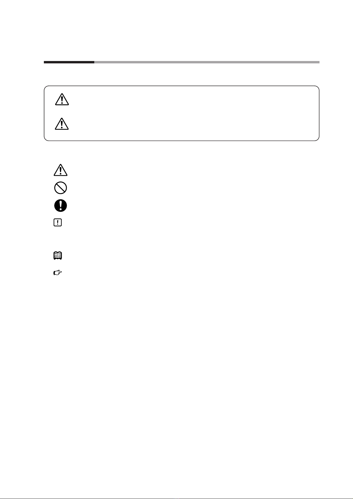
■To prevent injury to the operator and others, and to prevent property damage, the following types of safety
precautions are indicated:
■In describing the product, this manual uses the icons and conventions listed below.
Use caution when handling the product.
The indicated action is prohibited.
Be sure to follow the indicated instructions.
Handling Precautions:
Handling Precautions indicate items that the user should pay attention to when
handling the MCF.
Note:Notes indicate information that might benefit the user.
:This indicates the item or page that the user is requested to refer to.
(1), (2), (3): Numbers within parentheses indicate steps in a sequence or parts of an
explanation.
>>: Indicates the result of an operation, details displayed on the personal computer or
other devices, or the state of the device after operation.
03、P-07 This indicates 7-segment indication on the setup display.
[MODE] key:This indicates a key on the setup display.
WARNING Warnings are indicated when mishandling this product might result in
death or serious injury.
CAUTION Cautions are indicated when mishandling this product might result in
minor injury to the user, or only physical damage to the product.

ii
Safety Precautions
CAUTION
Before removing, mounting, or wiring the MCF, be sure to turn off the MCF and all con-
nected devices. Failure to do so might cause electric shock.
Do not disassemble the MCF.
Doing so might cause malfunction.
Wire this device properly, according to the standards given in this document, using the
specified types of wire and connection procedures. Failure to do so could result in mal-
function.
Use this device within the operating ranges given in the specifications for temperature,
humidity, voltage, vibration, shock, mounting direction, atmosphere, etc. Failure to do
so might cause malfunction.
Do not allow wire clippings, metal shavings, water, etc. to enter the device’s case. If
they do, they could cause faulty operation or device failure.

The Role of This Manual
iii
MCF Air Flowmeter User's Manual for Communication Functions
Manual No. CP-SP-1300E
This manual.
Those using the "communication functions" of the MCF series should read
this manual.
This manual describes an outline of communications, wiring, communication
procedures, a list of MCF series communication data, how to remedy
trouble, and communication specifications.
U
ser'sM
anual
C
P-UM-0
1
2
3E
WARNING
C
AUTI
O
N
WARNING
C
AUTI
ON
MCF Air Flowmeter User's Manual for Installation
Manual No. CP-UM-5498JE
This manual is supplied with the device. Personnel in charge of design and/or
manufacture of a system using this device must thoroughly read this manual.
This manual describes the safety precautions, installation, wiring, list of
parameters, and primary specifications.
MCF Air Flowmeter User's Manual for Installation and Configuration
Manual No. CP-SP-1276E
The manual describes the hardware and all functions of this device.
Personnel in charge of design, manufacture, operation, and/or maintenance
of a system using this device must thoroughly read this manual. It describes
installation, wiring, functions and settings, operating procedures, trou-
bleshooting, and specifications.
A total of three different manuals are available for the MCF. Read them as necessary for your specific requirements.
If a manual you require is not available, contact the azbil Group or its dealer.

Organization of This User's Manual
iv
This manual is organized as follows:
Chapter 1. OVERVIEW
This chapter describes communication outline of the MCF series.
Chapter 2. WIRING
This chapter describes RS-485 wiring methods to make a communication
link between the MCF series and other instruments.
Chapter 3. SETTING
This chapter describes MCF series communication settings.
Chapter 4. COMMUNICATION PROCEDURE
This chapter describes communication procedures, message configuration,
data read/write and signal timing operations.
Chapter 5. COMMUNICATION DATA TABLE
This chapter provides various data address tables for communications on
the MCF series.
Chapter 6. TROUBLESHOOTING
This chapter describes checkpoints to diagnose failures in MCF series com-
munications.
Chapter 7. SPECIFICATIONS
This chapter lists communication specifications for the MCF series.
Appendix
The appendix provides code table.

Contents
v
Conventions Used in This Manual
Safety Precautions
The Role of This Manual
Organization of This User's Manual
Chapter 1. OVERVIEW
■Features •••••••••••••••••••••••••••••••••••••••••••••••••••••••••••••••1-1
■Hardware configuration 1 ••••••••••••••••••••••••••••••••••••••••••••••1-1
■Hardware configuration 2 ••••••••••••••••••••••••••••••••••••••••••••••1-2
Chapter 2. WIRING
■Connection with 3-wire system ••••••••••••••••••••••••••••••••••••••••2-2
■Connection with 5-wire system ••••••••••••••••••••••••••••••••••••••••2-3
Chapter 3. SETTING
■Setting method•••••••••••••••••••••••••••••••••••••••••••••••••••••••••3-1
■Function settings ••••••••••••••••••••••••••••••••••••••••••••••••••••••3-2
Chapter 4. COMMUNICATION PROCEDURE
4-1 Outline of Communication Procedure and Messages••••••••••••••••••••••4-1
■Communication procedure•••••••••••••••••••••••••••••••••••••••••••••4-1
4-2 Command••••••••••••••••••••••••••••••••••••••••••••••••••••••••••••••••••4-8
■Function 0x03 (Read multiple words command) •••••••••••••••••••••••4-8
■Function 0x06, Write single register (write 1 word command) ••••••••4-10
■
Function 0x10, Write multiple registers (Write multiple words command)
4-11
4-3 Timing Specifications ••••••••••••••••••••••••••••••••••••••••••••••••••••4-14
■Timing specifications for instruction and response messages •••••••4-14
■RS-485 driver control timing specifications•••••••••••••••••••••••••••4-14
Chapter 5. COMMUNICATION DATA TABLE
5-1 Basic Communication Data Processing •••••••••••••••••••••••••••••••••••5-1
■Communication data types and formats •••••••••••••••••••••••••••••••5-1
■Communication data storage memory •••••••••••••••••••••••••••••••••5-1
■Data address •••••••••••••••••••••••••••••••••••••••••••••••••••••••••••5-2
■Number of data read / write ••••••••••••••••••••••••••••••••••••••••••••5-2
■Data unit and decimal point position•••••••••••••••••••••••••••••••••••5-2

5-2 Communication Data Table ••••••••••••••••••••••••••••••••••••••••••••••••5-3
■Device related data•••••••••••••••••••••••••••••••••••••••••••••••••••••5-3
■Operating status related data ••••••••••••••••••••••••••••••••••••••••••5-5
■Instantaneous flow rate related data •••••••••••••••••••••••••••••••••••5-6
■Integrated flow rate related data •••••••••••••••••••••••••••••••••••••••5-7
■Function setup related data ••••••••••••••••••••••••••••••••••••••••••••5-8
■Parameter setup related data •••••••••••••••••••••••••••••••••••••••••5-10
■Maintenance mode••••••••••••••••••••••••••••••••••••••••••••••••••••5-11
Chapter 6. TROUBLESHOOTING
Chapter 7. SPECIFICATIONS
■RS-485 specifications ••••••••••••••••••••••••••••••••••••••••••••••••••7-1
Appendix
■Code table ••••••••••••••••••••••••••••••••••••••••••••••••••••••••••App-1
vi

Chapter 1. OVERVIEW
The MCF series flowmeter (hereafter referred to as the MCF or the slave station) can communicate settings and
data with a host device, such as a PC or PLC (also called the master station). Users write a customized
communication program for this purpose.
■Features
The MCF has the following communications features.
•Remote data collection and parameter setting by RS-485 communications.
•Support for Modbus communications protocol (ASCII/RTU mode).
•With RS-485 communications, up to 31 slave stations can be connected to the
master station, which can read instantaneous flow rate and total flow values and
various settings from slave stations, and can also write settings to slave stations
using the user's own communications program.
•Uses “station addresses” for RS-485 communications to identify connected
•When the following procedure is completed during communication, various
data for the controller can be read or written:
(1) The master station transmits a request message to the slave station.
(2) The master station receives a response message from the slave station.
•The commands from master station to slave station are classified into two
types: read and write.
•The type of read/write data can be selected by data address.
■Hardware configuration 1
Master station
Slave station
(MCF)
Max. 31units
RS-232C / RS-485 converter
(CMC10L)
RS-485 (3-wire system)
1-1

1-2
■Hardware configuration 2
LAN (Ethernet)
Master station
Slave station
(MCF)
Max. 31units
MODBUS converter (gateway)
RS-485 (3-wire system)
Chapter 1. OVERVIEW
Table of contents
Other Azbil Measuring Instrument manuals

Azbil
Azbil MVC10A User manual

Azbil
Azbil MagneW Neo PLUS User manual

Azbil
Azbil ACTIVAL FVY5137J User manual

Azbil
Azbil MCF0080 User manual

Azbil
Azbil SLP-F7M User manual

Azbil
Azbil MagneW 3000 User manual

Azbil
Azbil MVF Series User manual

Azbil
Azbil AUR355 User manual

Azbil
Azbil SPG Series User manual

Azbil
Azbil MagneW FLEX+ User manual

Azbil
Azbil Micro Flow CMS9500 User manual

Azbil
Azbil MagneW Plus+ Series User manual

Azbil
Azbil SR100 User manual

Azbil
Azbil MCB10A User manual

Azbil
Azbil mF CMG Series User manual

Azbil
Azbil CY8100C1000 User manual

Azbil
Azbil MCW400A100 User manual

Azbil
Azbil MagneW Two-wire PLUS+ MTG15A User manual

Azbil
Azbil NWA300 User manual

Azbil
Azbil mF MVF Series User manual


