Aqua-Scope LoRaWAN AQSLWE01 Operating manual

Aqua-Scope Water
Monitor LoRaWAN
SKU: AQSLWE01
Version: 1.0.4
Product Description
The Aqua-Scope Water Monitor records all consumption of water in the home and it detects
damaging water leakages. To achieve this, the device applies advanced signal processing analyzing
water pressure waves traveling inside the pipes of the house water system.
A single sensor can monitor the whole home or apartment and communicates measured values and
alarms to a LoRaWAN network.
The current version of the Water Monitor is approved for single-family homes and multi-family homes
with one single water meter per apartment. 'Clinical Trials' are ongoing for installations in multi-
apartment homes with more than one water meter per apartment.
Installation Requirements
The Aqua-Scope Water Monitor watches the water pressure and water pressure waves (water noise) of
the home water installation system. The Aqua-Scope water microphone must be connected to the pipe
system at one single point in the home. Ideal connection points are edge valves located below sinks or
beside toilets. Alternatives are 1/4 inch revision openings on pressure reduction valves, shut off vales or
other installation gear. It is recommended to find a place as low in the home as possible (ideally
basement or first floor) but it is important to find a place 'after' the pressure valve (The main shut off
valve is typically positioned before the PRV and hence the water microphone shall not be installed on
Users and Installation Manual: Aqua-Scope Water Monitor LoRaWAN (AQSLWE01)
Copyright © 2021 Aqua-Scope Technologies, Sakala tn 7-2, 10141 Tallinn, Estonia, www.aqua-scope.com

this valve).
Further requirements are:
Next to the device is a mains power outlet for the USB power
plug.
The device expects a Pressure Reducing Valve (PRV)
installed in the home. The presence of a PRV is detected
automatically. If no PRV is present the device will still work but the functionality is limited. Please
refer to the manual section 'PRV Impact' for details.
Your home needs reasonable coverage by the LoRaWAN network of choice.
Mechanical Installation
To make it short and easy – the video on aqua-scope.com/install explains the installation of the Aqua-
Scope Water Monitor step by step:
1. In case there are two edge valves under the sink, please identify the cold-water supply. Just open
hot water and check which valve warms up.
2. Close the faucet and close the edge valve by turning clockwise.
3. Remove the metal hose from the edge valve using the 19 mm wrench supplied. You may want to
have a towel on hand to catch the water leaking from the end of the hose.
4. Mount the T-shaped connector on top of the edge valve and fasten it using the 19 mm wrench.
5. Connect the metal hose to the upper end of the connector
and fasten it using the 19 mm wrench.
6. Screw the Aqua-Scope microphone into the side opening of
the connector and fasten it by hand. There is no need to
make it super-tide.
7. Re-Open the edge valve by turning the knob anti-clockwise.
8. Please check all three connections for some seconds that
there are no leaks.
9. Attach the Aqua-Scope to a suitable location using double-
side tape and plug the microphone into one of the two
sockets on the main device. Attach the optional water
contact sensor to the other outlet if desired.
10. Power the device using the USB Power Plug. Please use the
power supply provided within the scope of delivery. This
very power supply has very low distortion factor required for precise measurements of pressure.
Pairing with the LoRaWAN Network
The device supports LoRaWAN Class A and OTAA activation. Setting configuration parameter #21 = 1
allows changing to Class C. Reboot of the device is needed after the configuration value was set.
Operating the device requires sufficient LoRaWAN coverage from your LoRaWAN provider of choice. Your
LoRaWAN service must register the new device before the OTAA operation. LoRaWAN OTAA requires
three device-specific keys for this process:
Users and Installation Manual: Aqua-Scope Water Monitor LoRaWAN (AQSLWE01)
Copyright © 2021 Aqua-Scope Technologies, Sakala tn 7-2, 10141 Tallinn, Estonia, www.aqua-scope.com

Device-EUI (unique key to identify this device)
Application-EUI (unique key to identify the service of this device)
App-Key (unique secret key to secure network connection setup)
You find all three keys printed out as label printed out inside the package. Furthermore, you find a QR-
code with the Device-EUI right in the device.
Using the service http://io.aqua-scope.com/lora/ you can download the complete set of keys plus
additional device information. Please contact [email protected] to receive your access
credentials for this service.
During pairing the LED will blink red/yellow. Once connected successfully the LED will glow green
indicating normal operation.
TTN Integration
The Things Network (TTN) is a free community based LORAWAN network with
global reach. If there is a TTN Gateway near your home you can use the water
sensor without any further hardware If no – may be this is a good reason to
join the community with your own gateway.
After the registration of the device with TTN please use the “HTTP Integration”
to forward all data to ‚https://io.aqua-scope.com/lora/in.php‘. Convenient
access for test purposes is possible using ‚https://io.aqua-scope.com/lora/ui.php?dev=DEVICE_EUI‘. The
link ‚https://io.aqua-scope.com/lora/lora.zip‘ allows downloading the scripts for change, inspection and
further use on own server and integrate the data into your own application.
Please note that the mentioned scripts can only be used for devices from Aqua-Scope. Device EUIs from
other manufacturers will not be processed.
Functions and Usage
Water Consumption
The device will report each consumption of water including the duration plus the consumed amount. This
function is deactivated on default to comply with "fair use" policy of most LoRaWAN networks but can be
activated using configuration parameter #21 bit 4.
Ambient Sensors
The current water pressure, the ambient temperature and the incremental water consumption since the
time of the last report is sent every 15 minutes. The reporting period is defined in configuration
parameter #29.
Leackage Detection
To detect leaks some water must have escaped from the water system. Hence, leak detection does not
protect you from leaks but minimizes the damage of leaks. Damage happens if a certain amount of
Users and Installation Manual: Aqua-Scope Water Monitor LoRaWAN (AQSLWE01)
Copyright © 2021 Aqua-Scope Technologies, Sakala tn 7-2, 10141 Tallinn, Estonia, www.aqua-scope.com
water has enough time to impact construction material and furniture.
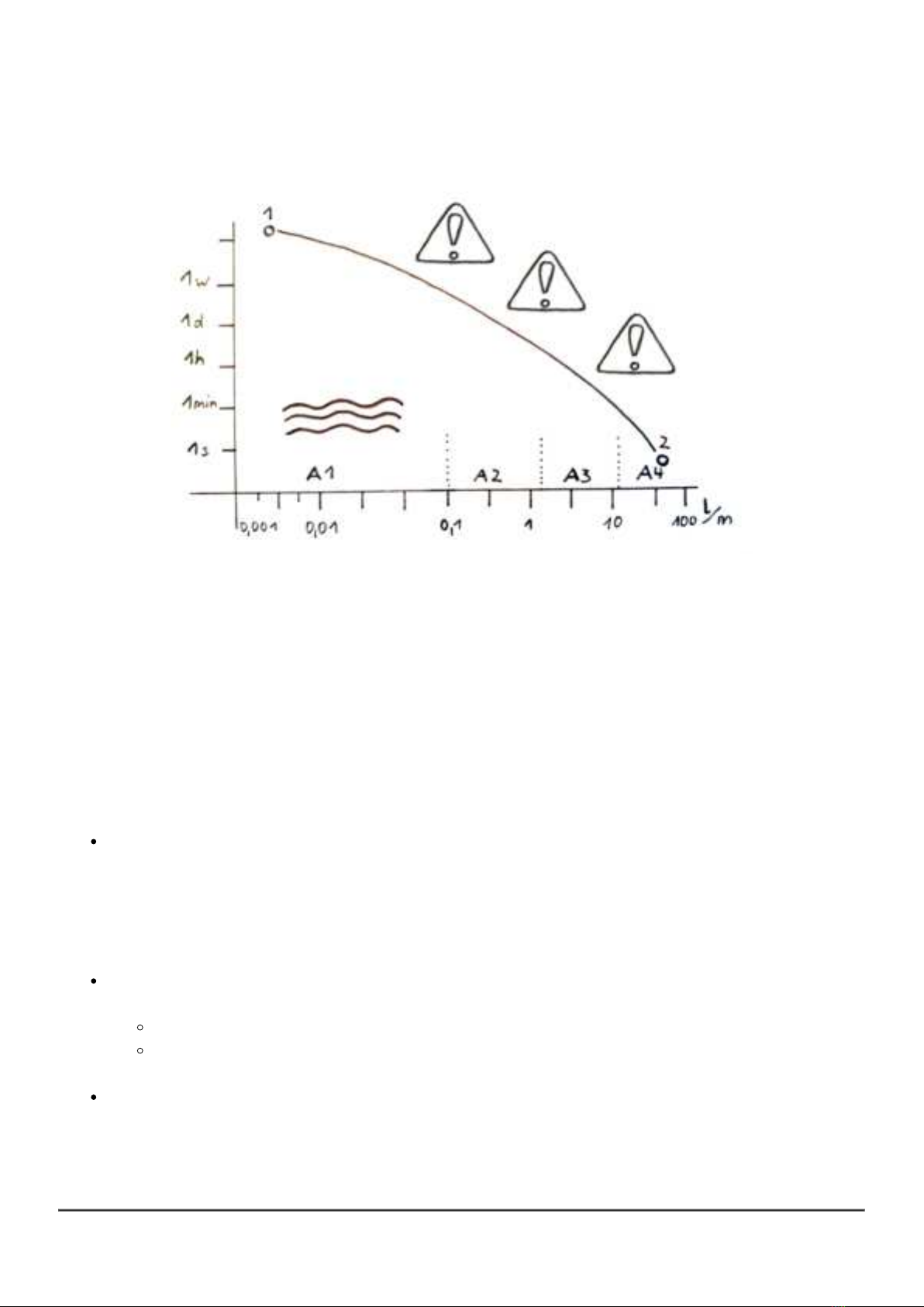
The diagram above shows the relationship between the speed of water (in liters/minute) and the time
this water flows out. The thick curve marks the area where damage will happen (about 10 liters of water,
one full bucket). The required reaction time to a detected leak depends on the speed of the water. For
micro leakages with very low speed of water (point 1 in the diagram) its acceptable to act after few days
or even weeks while a fatal burst of a pipe requires a reaction within few seconds (point 2 in the
diagram).
Aqua-Scope uses different techniques to identify leaks in four different scenarios (A1 - A4) characterized
by their speed of water. The lines between the area are determined by calibration. After initial calibration
the are constantly are re-adjusted to adapt the device to changing conditions of the water system. The
four sub-areas result in different alarms because the user action on these alarms may be different.
All normal water outlets in a home limit the speed of water. Even parallel consumption of water will
not result in speed of water beyond a certain level. In case the system detects a very high speed
of water a possible root cause is a bursting pipe (Section A4). Depending on the measured speed
of water the Aqua-Scope will issue a Heavy Flow-Alarm after few seconds. Please note that an
interruption of the water supply or a manual shut-off of the water will result such this alarm type
too since the Aqua-Scope Water Monitor must assume that the water disappeared somewhere.
The „Usage“-scenario (section A3) is defined by speeds of water typically for normal water
consumption of toilets, appliances, or faucets. Two thresholds define the alarm condition:
Max time in seconds, factory-default is 900 s = 15 m
Max amount of water in liter, factory-default is 200 liters
Exceeding these thresholds will cause a Usage-Alarm.
Additional protection is provided by the external wired water contact sensor, connected to one of
the two sockets of the Aqua-Scope. This will recognize e.g. spillovers or other loss of water. A
Flood-Alarm is sent out in this case.
Users and Installation Manual: Aqua-Scope Water Monitor LoRaWAN (AQSLWE01)
Copyright © 2021 Aqua-Scope Technologies, Sakala tn 7-2, 10141 Tallinn, Estonia, www.aqua-scope.com

The most dangerous and most common type of leaks are caused by a chemical reaction in the
water pipe leading to small orifice, also called micro-leaks (section A1). Since these orifices are
very tiny in the beginning, they are usually not seen. However, these very tiny leaks indicate a
much larger problem later on. The device has a built-in process to detect these small leaks. It is
called Pipe-Check. It requires to shut off the water for about 3 minutes. The application controls
this process by shutting off the water automatically (or advise the user to manually shut off before
triggering the pipe check). The completion of the pipe check is indicated with an uplink status
command or in case of a problem a Pipe-Check Alarm. The alarm includes the estimated speed
of water in ml /min plus the estimated elevation of the leak relative to the elevation of the water
microphone.
The “Drip”-scenario (section A2) defines flow speeds between about 100 ml/m and 2000 ml/m.
This is still quite low, but a Pipe-Check would come too late here. Hence, this range is monitored
permanently and detected leaks or dripping faucets will cause a Drip-Alarm within minutes.
Additional Monitoring
The system is permanently monitoring the water to detect pattern indicating a jamming toilet flap.
In this case a Jamming-Alarm is issued.
If the water pressure is too high the pipes may be damaged in the home. The Aqua-Scope will
determine automatically the highest acceptable pressure and report an Overpressure-Alarm if
this threshold is exceeded.
The internal temperature sensor allows issuing a Frost-Alarm when a certain threshold for frost
danger is hit. The factory default value for this threshold is 4 °C.
LED-Signals
Slow glowing of the green LED: Normal operation, no flow of water
Faster blinking of the green LED: Flow of water
Red fast blinking: Alarm
Red/Yellow/Green LED light up one time with beep right after power-up: ongoing Pipe-Check
Green/red blinking: connection to wireless network pending
Sequential red LED blink: Fatal hardware error
1-time blinking: general error
2 times blinking: FLASH memory error
3 times blinking: RAM memory error
4 times blinking: ADC access error
5 times blinking: LORA access error
PRV Impact
An installed pressure reducing valve (PRV) is common in almost all contemporary European home water
installations. Without PRV the Aqua-Scope Water Monitor is still applicable but some functions are limited.
Working: Pressure Monitor, Temperature Monitor, Flood-Alarm, Frost-Alarm, Overpressure-Alarm,
Micro Leak Testing
Not Working: Drip-Alarm
Users and Installation Manual: Aqua-Scope Water Monitor LoRaWAN (AQSLWE01)
Copyright © 2021 Aqua-Scope Technologies, Sakala tn 7-2, 10141 Tallinn, Estonia, www.aqua-scope.com

Less Precise: Usage Alarm, Water Consumption Metering, Jamming-Alarm
Alarm and Alarm Clearing
All alarms are indicated with
a buzzer sound on the device,
a red LED blinking on the device,
a LoRaWAN alarm message sent to the LoRaWAN Application Server
Alarms are cleared automatically if the reason for the alarm disappeared.
Only the Flow-Alarm must be cleared by a wireless command or pushing
the single button on the device even when the sensor does not have
contact with water anymore. The recessed round part on the middle of the
device is the touch button.
If no alarm is cleared pressing the button will issue a heartbeat signal sent
to the LoRaWAN network server.
Scope of Delivery
Aqua-Scope Water Monitor main device
Aqua-Scope water microphone with 80 cm cable and audio jack
3/8 Inch water pipe connector (T-shaped)
One external water contact sensor with cable and audio jack
USB power cable and power supply
19 mm wrench to unfasten and fasten the 3/8 Inch connections of the pipe connector
Manual
Reset to Factory Default
The factory default is indicated by a green/red blinking LED. To return to factory default push the button
right after the initial buzzer beep (but not earlier!) and keep it pushed for 5 seconds. 4 short beeps will
help you count. After 5 seconds you will see three short green LED pulses with a low-frequency sound.
Now release the button! The recessed round part on the middle of the device is the touch button.
This process will delete all device and network settings.
LoRaWan Payload Commands
LoRaWAN commands can be daisy chained into the payload up to the defined maximum payload size of
51 bytes. This mean that for all commands sent to defined number of bytes in the payload is required to
avoid misinterpretation of command and/or command values in the receiver side. All uplink and downlink
commands use FPort=1.
Users and Installation Manual: Aqua-Scope Water Monitor LoRaWAN (AQSLWE01)
Copyright © 2021 Aqua-Scope Technologies, Sakala tn 7-2, 10141 Tallinn, Estonia, www.aqua-scope.com

Uplink Command Version Report: 0x03 - HW - SW_MSB - SW_BYTE2 - SW_BYTE3 - SW_LSB (6
Byte)
This command reports the version of the device. It is sent unsolicited as first command during boot-up
and as replying command to downlink command Version Get. HW is a single byte indicating the version
of the hardware, the 32-Bit SW value is the version of the firmware representing the compile date.
Example: 0x03 0x05 0x00 0x03 0x10 0xdd => Device Hardware Version 5, Firmware 200925 (firmware
was created on 25th of September 2020)
Uplink Command Configuration Report: 0x04 - IDX - VAL_MSB - VAL_LSB (4 Byte)
This command reports a configuration parameter of the device: IDX is the number of the configuration
parameter. The 16 Bit VAL is the parameter itself. Configuration parameters are always 16 Bit Values.
The table below describes the configuration parameters and its values.
Uplink Command Sensor Report: 0x06 - ID - VAL_MSB - VAL_LSB (4 Byte)
This command reports sensor values. The ID indicates the sensor type and defines the format of the 16-
Bit VAL. Possible sensor types are:
0x01: Temperature: VAL is temperature in 1/10 Degree Celsius. Example: 0x06 0x01 0x20 0x20
=> Temperature 0x00CD = 205 = 20.5 C.
0x03: Uptime: VAL is the number of minutes after last boot
0x10: Water Pressure (1) : VAL is unsigned water pressure in mBar. Example: 0x10 0x011 0x0D
0x48 => Pressure 0x0D48 = 3400 = 3.4 Bar.
0x11: Water Consumption: VAL is water consumption in Liters since last report
0x15: Average Water Pressure (1) : VAL is unsigned water pressure in mBar. Example: 0x10 0x011
0x0D 0x48 => Pressure 0x0D48 = 3400 = 3.4 Bar.
0x16: Minimum Water Pressure (1) : VAL is unsigned water pressure in mBar. Example: 0x10
0x011 0x0D 0x48 => Pressure 0x0D48 = 3400 = 3.4 Bar.
0x17: Maximum Water Pressure (1) : VAL is unsigned water pressure in mBar. Example: 0x10
0x011 0x0D 0x48 => Pressure 0x0D48 = 3400 = 3.4 Bar.
0x20: Water Pressure (sensor 2) : VAL is unsigned water pressure in mBar. Example: 0x10 0x011
0x0D 0x48 => Pressure 0x0D48 = 3400 = 3.4 Bar.
0x25: Average Water Pressure (sensor 2) : VAL is unsigned water pressure in mBar. Example: 0x10
0x011 0x0D 0x48 => Pressure 0x0D48 = 3400 = 3.4 Bar.
0x26: Minimum Water Pressure (sensor 2) : VAL is unsigned water pressure in mBar. Example:
0x10 0x011 0x0D 0x48 => Pressure 0x0D48 = 3400 = 3.4 Bar.
0x27: Maximum Water Pressure (sensor 2) : VAL is unsigned water pressure in mBar. Example:
0x10 0x011 0x0D 0x48 => Pressure 0x0D48 = 3400 = 3.4 Bar.
Uplink Command Water Status Report: 0x07 - STATE - VAL1_MSB - VAL1_LSB - VAL2_MSB -
VAL2_LSB (6 Byte)
This command reports every single water flow event and the result of a Pipe-Check. STATE contains the
status of the operation and defines the meaning of the two 16-bit values.
Users and Installation Manual: Aqua-Scope Water Monitor LoRaWAN (AQSLWE01)
Copyright © 2021 Aqua-Scope Technologies, Sakala tn 7-2, 10141 Tallinn, Estonia, www.aqua-scope.com

1: Water Flow complete, VAL1 contains the duration of the water flow in seconds, VAL 2 contains
the amount of water consumed in Liter. The amount of water can be adjusted using a correction
value of calibration parameters #16 and #17 (PRV present) or #26 and #28 (no PRV present).
2: Pipe-Check completed without Alarm. VAL1 contains the pressure decay, VAL 2 is the water
pressure at the end of the Pipe-Check.
3: Pipe-Check completed with Alarm. VAL1 contains the estimated water loss in ml/h, VAL 2
contains the estimated position of the leak in meters above the position of the Aqua-Scope
microphone.
4: Pipe-Check aborted because of unexpected regular water use. VAL1 and VAL2 have no meaning.
5: Pipe-Check aborted because of the preparation of hot water. During this time it is not possible to
perform a Pipe-Check. VAL1 and VAL2 have no meaning.
Uplink Command Logging: 0x08 - V1 - V2 - V3 (51 Byte)
This command is used to send certain logs to the server. V1 defines log event, V2 and V3 may add
certain logging values.
1: Device in Factory Default
2: Pressure Sensor Lost
3: Pressure Sensor reconnected
4: Quick Calibration done, V2 = average pressure in mBar, V3 = average noise in mBar
5: Standard Calibration done, V2 = average pressure in mBar, V3 = average noise in mBar
6: Long Term Calibration, V2 = average pressure in mBar, V3 = average noise in mBar
7: Pressure Reduction Valve Detection: V2 = 1, PRV present, V2 = 0, no PRV
Uplink Command Calibration Report: 0x09 - STATUS - VAL1_MSB - VAL1_LSB - VAL2_MSB -
VAL2_LSB (6 Byte)
The Initial calibration is required to find critical parameters for the detection of water flow. Prior to the
completion of the initial calibration most of the functions of the Aqua-Scope monitor are disabled. The UI
will trigger starting the calibration process sending a downstream command 0x09 with status = 2. The
device will prepare for the calibration and, once ready, answers with status = 3. Now the user is required
to flush the toilet once. The completion of the calibration is indicated (latest after 5 minutes but can be
earlier) with status = 4. Failures is reported with status = 5. After 24 hours a second round of calibration
will finish, and the result are report using status = 6. After this the system will constantly recalibrate in
the background but not report any status changes.
Status 3: Calibration pending for maximum 5 minutes
Value 1: max calibration time in seconds
Value 2: ignore
Status 4: Calibration Successful
Value 1: no PRV found (= 1) or PRV found (= 2)
Value 2: Standard pressure in mbar
Status 5: Calibration failed
Value 1: Assumed pressure during water flow
Users and Installation Manual: Aqua-Scope Water Monitor LoRaWAN (AQSLWE01)
Copyright © 2021 Aqua-Scope Technologies, Sakala tn 7-2, 10141 Tallinn, Estonia, www.aqua-scope.com

Value 2: Standard pressure in mbar
Status 6: Calibration Final
Value 1: max pressure drop on PRV operation
Value 2: Standard pressure in mbar
Uplink Command Alarm Report: 0x0b - STATE - TYPE - VAL_MSB - VAL_LSB (5 Byte)
This command reports starts and end of alarms. The STATE-Byte indicate the status of the alarm (0x01 =
active, 0x00 = inactive). The TYPE Byte indicates the type of alarm and defines the content of the 16 Bit
VAL.
0x01: Flow: Water sensor recognized water, VAL is 0x01 or 0x00.
0x02 Freeze: Ambient temperature dropped below threshold. VAL is actual temperature.
0x03: Usage: Usage exceeds threshold or max. time or max water flow. VAL is the time in s.
0x04: Heavy Flow: Unusual heavy water flow, usually indicates a pipe burst. VAL is an estimation
of the water loss in mLiter/min.
0x05: Jamming: A jamming toilet flap is detected. The value is 0x00.
0x06: Overpressure: Water pressure exceeds the calibrated maximum water pressure. The
threshold can be changed in configuration parameter #6. VAL is the measures pressure value.
0x07: Drip:
0x08: Pipe-Check Result: VAL_MSB is an indicator for the estimated loss of water in milliliters/hour.
VAL_LSB is an indicator for the estimated height of the location of the micro leakage measured
from the height of the sensor in the home.
0x0e: Sensor Missing: There is no external sensor connected to the Aqua-Scope Monitor.
0x0f: Pressure Missing: An external sensor is connected to the Aqua-Scope Monitor but the sensor
head is not connected to a water pipe under pressure.
The configuration parameter #19 defines which parameter is active. Inactive alarms will not be reported
and will not cause any other indications (buzzer, led).
Downlink Command System Commands: 0x01 - CMD (2 Byte)
This command sends a system command to the devices. CMD defines the type of command:
CMD = 0x01: System restart
CMD = 0x02: System Reset - back to factory default
CMD = 0x03: Start Pipe-Check. The behavior of the Pipe-Check can be defined in configuration
parameters.
Downlink Command Version Get: 0x03 - (1 Byte)
This command calls for a Version Report sent upstream
Downlink Command Configuration Set: 0x04 - IDX - VAL_MSB - VAL_LSB (4 Byte)
This command allows setting configuration parameters of the device: IDX is the number of the
configuration parameter. The 16 Bit VAL is the parameter itself. Configuration parameters are always 16
Bit Values. The table below describes the configuration parameters and its values.
Users and Installation Manual: Aqua-Scope Water Monitor LoRaWAN (AQSLWE01)
Copyright © 2021 Aqua-Scope Technologies, Sakala tn 7-2, 10141 Tallinn, Estonia, www.aqua-scope.com

Downlink Command Calibration Set: 0x09 - (1 Byte)
This command starts the initial calibration process. On calibration process please refer to the description
of the uplink command
Downlink Command Alarm Clear: 0x0b - TYPE (2 Byte)
This command clears an alarm. TYPE is the type of alarm to be cleared. Type = 0 clears all active alarms.
For other types of alarms to be cleared please refer to the uplink command 0x0b.
Downlink Command Configuration Get: 0x14 - IDX (2 Byte)
This command allows reading the configuration value IDX. The device will respond with an upstream
command Configuration Report
Configuration Parameters
All Configuration Parameters are 2 Byte values that can be set and read out using LoRaWAN 'config get'
and 'config set' commands.
Parameter 5 (0x5): Water Standard Pressure (Default: 0x0dac = dec 3500)
This parameter is for information only. The pressure value is automatically set at initial calibration and
may change from time to time as a result of ongoing calibration. The value is provided in mBar
regardless of the scale settings in parameter #21.
Parameter 6 (0x6): Over-Pressure Warm threshold (Default: 0x1f40 = dec 8000)
An overpressure alarm is sent as an uplink message when the current pressure exceeds this threshold.
The threshold value is automatically set 24 hours after initial setup during calibration and may change
from time to time as a result of ongoing calibration. The value is accepted in mBar regardless of the
scale settings in parameter #21.
Parameter 7 (0x7): Over-Pressure Max Warm threshold (Default: 0x1f40 = dec 8000)
An overpressure alarm is sent as an uplink message when the current pressure exceeds this threshold.
This threshold value is NOT changed by calibration. The value is accepted in mBar regardless of the
scale settings in parameter #21.
Parameter 8 (0x8): Under-Pressure Warm threshold (Default: 0x1f40 = dec 8000)
A heavy flow alarm is sent as an uplink message when the current pressure falls below this threshold for
certain time. The threshold value is automatically set 24 hours after initial setup during calibration and
may change from time to time as a result of ongoing calibration. The value is accepted in mBar
regardless of the scale settings in parameter #21.
Parameter 9 (0x9): Jamming Toilet (Default: 0x00c8 = dec 200)
This parameter defines the max time in seconds for 10 consecutive small water consumption event
Users and Installation Manual: Aqua-Scope Water Monitor LoRaWAN (AQSLWE01)
Copyright © 2021 Aqua-Scope Technologies, Sakala tn 7-2, 10141 Tallinn, Estonia, www.aqua-scope.com
Table of contents
Other Aqua-Scope Measuring Instrument manuals


