
Analytical Technology A15 User manual

Model A15/76
Turbidity Monitor
Home Office EuropeanOffice
Analytical Technology, Inc. ATI (UK) Limited
6 Iron Bridge Drive Bank Chambers, 33 Stamford St.
Collegeville, PA 19426 Mossley, Ashton-u-Lyne OL50LL
Ph:(800) 959-0299 Ph: 0800-018-4020
(610) 917-0991 + 44 (0) 1457 832800
Fax: (610) 917-0992 Fax:+ 44 (0) 1457 839500

PRODUCT WARRANTY
Analytical Technology, Inc. (Manufacturer) warrants to the Customer that if any part(s)
of the Manufacturer's products proves to be defective in materials or workmanship within the
earlier of 18 months of the date of shipment or 12 months of the date of start-up, such
defective parts will be repaired or replaced free of charge. Inspection and repairs to products
thought to be defective within the warranty period will be completed at the Manufacturer's
facilities in Oaks, PA. Products on which warranty repairs are required shall be shipped freight
prepaid to the Manufacturer. The product(s) will be returned freight prepaid and allowed if it is
determined by the manufacturer that the part(s) failed due to defective materials or
workmanship.
This warranty does not cover consumable items, batteries, or wear items subject to
periodic replacement including lamps and fuses.
Gas sensors, except oxygen sensors, are covered by this warranty, but are subject to
inspection for evidence of extended exposure to excessive gas concentrations. Should
inspection indicate that sensors have been expended rather than failed prematurely, the
warranty shall not apply.
The Manufacturer assumes no liability for consequential damages of any kind, and the
buyer by acceptance of this equipment will assume all liability for the consequences of its use
or misuse by the Customer, his employees, or others. A defect within the meaning of this
warranty is any part of any piece of a Manufacturer's product which shall, when such part is
capable of being renewed, repaired, or replaced, operate to condemn such piece of
equipment.
This warranty is in lieu of all other warranties (including without limiting the generality of
the foregoing warranties of merchantability and fitness for a particular purpose), guarantees,
obligations or liabilities expressed or implied by the Manufacturer or its representatives and by
statute or rule of law.
This warranty is void if the Manufacturer's product(s) has been subject to misuse or
abuse, or has not been operated or stored in accordance with instructions or if the serial
number has been removed.
Analytical Technology, Inc. makes no other warranty expressed or implied except as
stated above.

Model A15/76 Turbidity Monitor
O & M Manual
Rev. E, 09/06 -3 -
TABLE OF CONTENTS
UNPACKING.............................................................................................................................................4
INTRODUCTION.......................................................................................................................................5
FIGURE 1 -TURBIDITY SYSTEM WITH SUBMERSION SENSOR (ATI-0471)..................................5
SPECIFICATIONS....................................................................................................................................6
Electronics Unit............................................................................................................................6
Sensor..........................................................................................................................................6
INSTALLATION.........................................................................................................................................7
FIGURE 2 - PANEL MOUNT MONITOR DIMENSIONS & INSTALLATION (ATI-0124,125) .......7
FIGURE 3 - NEMA - 4X WALL MOUNT DIMENSIONS & INSTALLATION (ATI-010) ..................8
FIGURE 4 - HANDRAIL MOUNTING ASSEMBLY FOR NEMA 4X ENCLOSURE (ATI-043)..............9
FIGURE 5 FLOWCELL DIMENSIONS (ATI-0435)............................................................................10
FIGURE 6 EXPLODED FLOWCELL AND SENSOR ASSEMBLY (ATI-0470) .................................10
FIGURE 7 – FLOW TEE RECOMMENDED PIPING (ATI-0793)........................................................11
FIGURE 8 – FLOW TEE TYPICAL CONFIGURATION (ATI-0513)....................................................12
FIGURE 9 – FLOW TEE ASSEMBLY (ATI-0542)...............................................................................13
FIGURE 10 - SUBMERSIBLE SENSOR MOUNTING (ATI-0447)......................................................14
ELECTRICAL CONNECTIONS................................................................................................................15
FIGURE 11 – TURBIDITY SYSTEM CONNECTIONS (ATI-0443).....................................................15
FIGURE 12– TURBIDITY SYSTEM WITH JUNCTION BOX CONNECTIONS (ATI-0445)................16
START-UP................................................................................................................................................17
Front Panel Lock..........................................................................................................................18
CONFIGURATION....................................................................................................................................19
OPERATION.............................................................................................................................................21
Setting Zero..................................................................................................................................21
Setting Sensitivity (Span).............................................................................................................22
CONTROL & ALARM OUTPUTS .............................................................................................................23
Control Relays..............................................................................................................................23
Alarm Relay..................................................................................................................................24
Auto/Manual Operating Mode......................................................................................................24
Check Signal Display...................................................................................................................25
MAINTENANCE........................................................................................................................................26
Sensor Maintenance....................................................................................................................26
SPARE PARTS LIST - MODEL A15/76....................................................................................................27

Model A15/76 Turbidity Monitor
O & M Manual
Rev. E, 09/06 -4 -
UNPACKING
When you receive your Turbidity Monitor, open the shipping package and inspect the contents to be sure
that all items have been received. The items shipped will depend on the type of system ordered. The following is
a list of items normally supplied with standard flow type systems.
Quantity 1 - Model A15/76 Turbidity Monitor Electronics, NEMA 4X (if ordered)
Quantity 1 - Turbidity Sensor
Quantity 1 - Flowcell Assembly with mounting bracket
Quantity 1 - Sensor cable assembly, 30 feet
Quantity 1 - Operation & Maintenance Manual
If you ordered a system with a submersible sensor, your package will not contain a flowcell assembly.
Instead, you will receive a two-part submersion sensor holder.
In addition to the standard items listed above, any additional spare parts or spare sensors that were
ordered separately will be included. Compare the contents of the shipping container with the packing list. The
items listed above are the standard components that are included with every standard A15/76 Turbidity monitor.
Any other items will be listed separately on the packing list. Check the contents of the shipping container
carefully to insure that nothing is overlooked. Should you find anything missing from the shipment, immediately
contact the ATI sales department by calling either 800-959-0299 or 610-917-0991. If you prefer, you may send a
fax describing the error to 610-917-0992.
Model A15/76 Turbidity Monitor
O & M Manual
Rev. E, 09/06 -5 -
INTRODUCTION
The Model A15/76 is an on-line monitoring system designed for the continuous measurement of the
turbidity of an aqueous stream. It is primarily intended for monitoring turbidity in drinking water or wastewater
effluent. The monitor provides display ranges from 0-4.000 NTU up to 0-4000 NTU. The display range used for a
given application is user programmable, and an auto-ranging feature allows the display of high turbidity values,
even when programmed for low range use. A15/76 monitors are designed to operate on samples at
temperatures from 0°to 50 °C and pressures of 0-100 PSIG. The measured turbidity is displayed on a backlit
liquid crystal display on the front of the instrument.
The sensor used in the A15/76 system measures turbidity using a 90-degree light scattering technique.
An infrared LED light source emanates from a planer surface and a detector in the same plane measures light
scattered at 90 degrees to the incident light beam. An automatic zero correction system allows measurement of
very low turbidity values with excellent zero stability. The sealed flowcell used for low level measurements is
designed to allow measurement of a pressurized sample in order to avoid errors caused by bubbles formed when
sample pressures are reduced.
For wastewater application, or where a submersible measurement is desired, the turbidity sensor is
supplied with a special holder to minimize ambient light effects. The submersible assembly eliminates the need
for sample pumps, and will operate at turbidity values up to 4000 NTU. For applications where fouling is a
problem, a special “Auto-Clean” version of the turbidity sensor is available. Contact your ATI representative for
details.
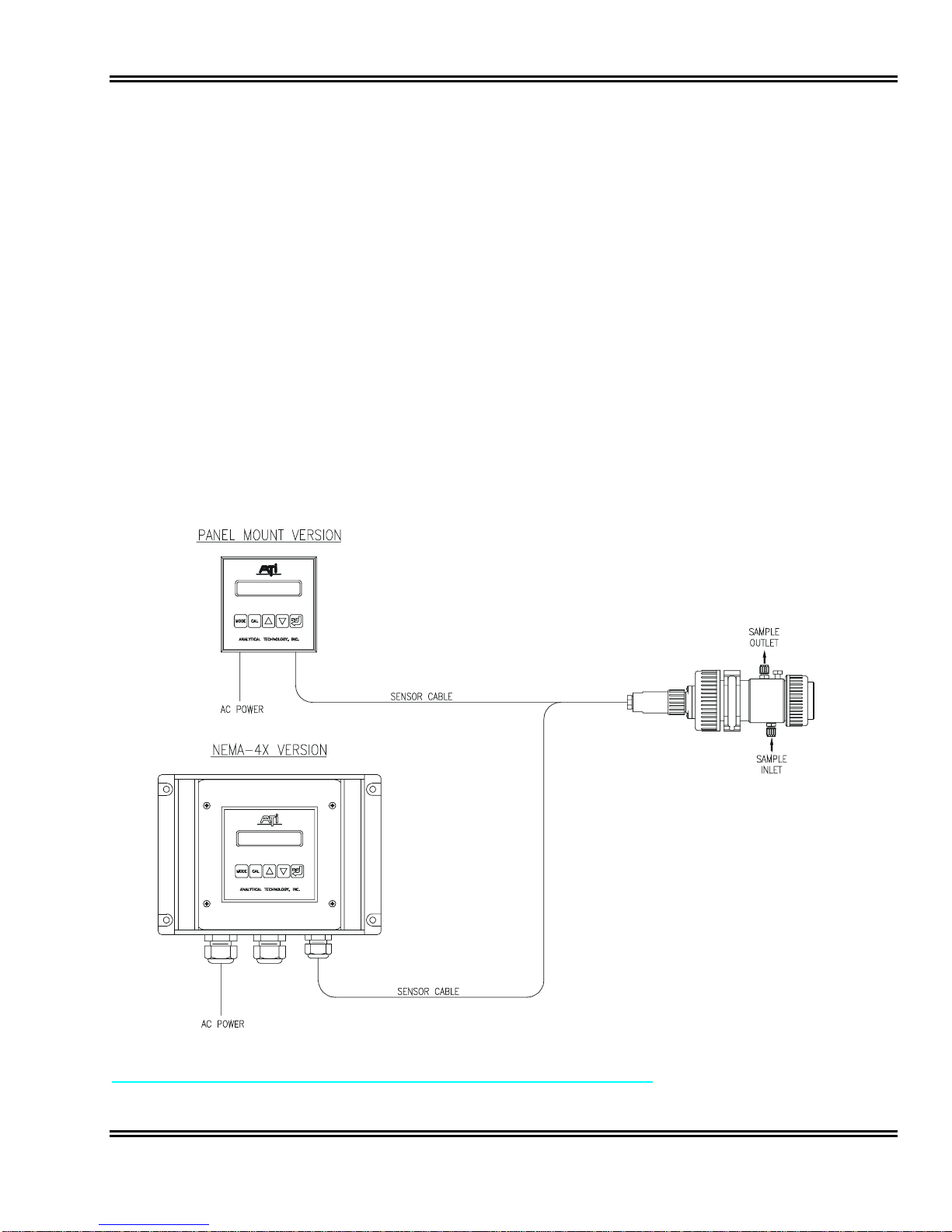
FIGURE 1 -TURBIDITY SYSTEM WITH SUBMERSION SENSOR (ATI-0471)

Model A15/76 Turbidity Monitor
O & M Manual
Rev. E, 09/06 -6 -
SPECIFICATIONS
Electronics Unit
Range: 4/400 NTU (0-4.000, 0-40.00, 0-400.0)
40/4000 NTU (0-40.00, 0-400.0, 0-4000)
9/999 mg/l (or PPM) SiO2(0-9.999, 0-99.99, 0-999.9)
99/9999 mg/l (or PPM) SiO2 (0-99.99, 0-999.9, 0-9999)
Auto-ranging over 3 decades of concentration
Sensor Type: 90°Scatter (nephelometer)
Accuracy: ± 5% of reading or ± 0.02 NTU, whichever is greater, on 40/400 scale
± 10% of reading or ±2 NTU, whichever is greater, on 400/4000 scale
Linearity: 0.1% of F.S.
Display: 16 character alphanumeric backlit LCD
Control Relays: Two SPDT relays, 5A @ 220 VAC resistive.
Programmable deadband and time delay.
Control Mode: On/Off
Alarm Relay: Independent SPDT relay, 5A @ 220 VAC resistive.
Programmable for actuation on high/low values or control system failure.
Also indicates dry cell condition, fouled sensor, or high ambient light
Analog Output: Isolated 4-20 mA, 600 ohm maximum load. Programmable output range user set
Operating Conditions: -20° to +55° C., 0-95% R.H. non-condensing.
Power: 110/220 VAC ±10%, 50/60 Hz.
Enclosure: Panel mount standard
NEMA 4X wall mount optional
Sensor
Range: 0-4000 NTU
Measurement angle: 90-degree scatter (nephelometric)
Response Time: 95% in 10 seconds
Power: ±12 VDC supplied by monitor, preamplifier in sensor head
Temperature Limits: 0 - 50° C.
Pressure Limits: 0 - 100 PSIG
Connections: 7-conductor sensor cable to monitor, 30 feet standard, 350 feet maximum
Sensor Materials: Delrin body, Acrylic optical windows
Flowcell Materials: PVC
Flowcell Connections: 4 mm tube fittings (black tubing supplied)
Flowcell Pressure: 0-100 PSIG
Flowcell Temperature: 0-60° C
Model A15/76 Turbidity Monitor
O & M Manual
Rev. E, 09/06 -7 -
INSTALLATION
The main installation requirements for ATI’s Turbidity Monitor are mechanical installation, and connection
of power to the monitor. Figure 1 on page 5 shows a schematic of a typical installation of a complete system.
The monitor should be located near the sensor in order to use the standard 30 foot sensor cable supplied with the
system. Longer cable runs can be accommodated using a junction box and additional 7-conductor cable.
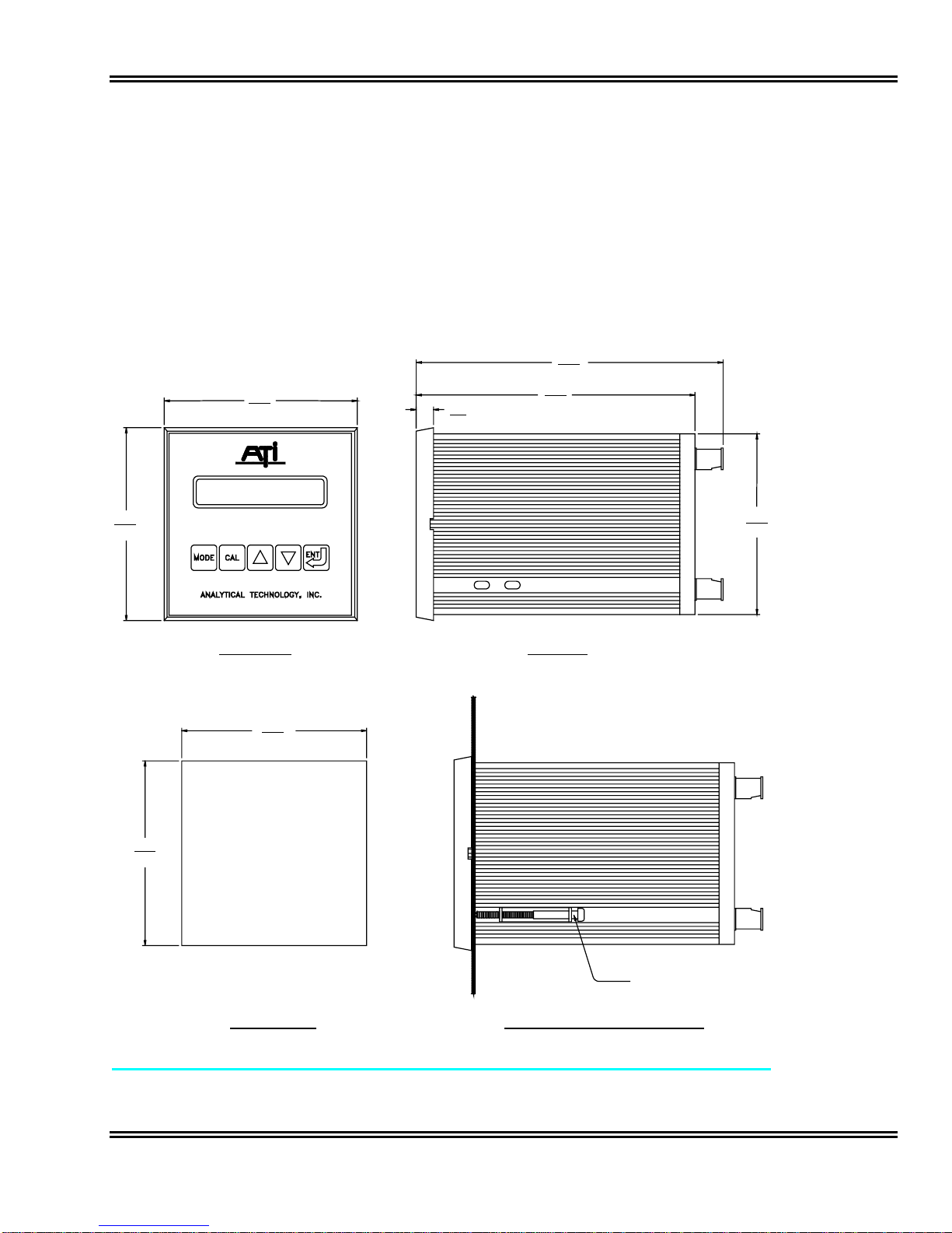
Figure 2 provides details on the mechanical installation of the standard panel mount electronic assembly.
The panel cutout must be made accurately as the cutout tolerance is small. Panel mounting brackets are
included with the monitor and are attached as shown below.
6
.
10
"
155mm
5.46"
139mm
.34"
8.6mm
3.54"
90mm
3.78"
96mm
SIDE VIEWFRONT VIEW
3.78"
96mm
MOUNTING BRACKETS
(TYPICAL 2 PLACES)
MOUNTING BRACKET INSTALLATIONPANEL CUTOUT
3.60"
91.4mm
3.60"
91.4mm
FIGURE 2 - PANEL MOUNT MONITOR DIMENSIONS & INSTALLATION (ATI-0124,125)
Model A15/76 Turbidity Monitor
O & M Manual
Rev. E, 09/06 -8 -
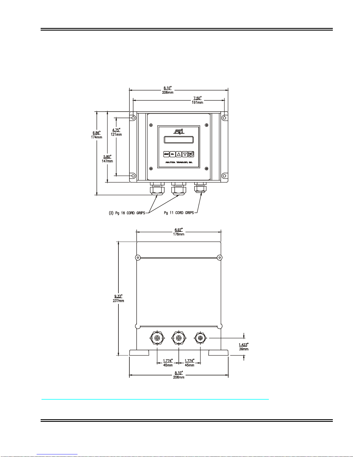
The optional NEMA 4X wall mount enclosure is a Molded Plastic ABS unit that bolts directly to a wall or
other flat surface. The enclosure is supplied with special mounting bracket for convenience in mounting the
enclosure. A hinged door on the front of the enclosure provides access to operating controls, and a hinge on the
back section for convenience in wiring the unit.
FIGURE 3 - NEMA - 4X WALL MOUNT DIMENSIONS & INSTALLATION (ATI-010)
Model A15/76 Turbidity Monitor
O & M Manual
Rev. E, 09/06 -9 -
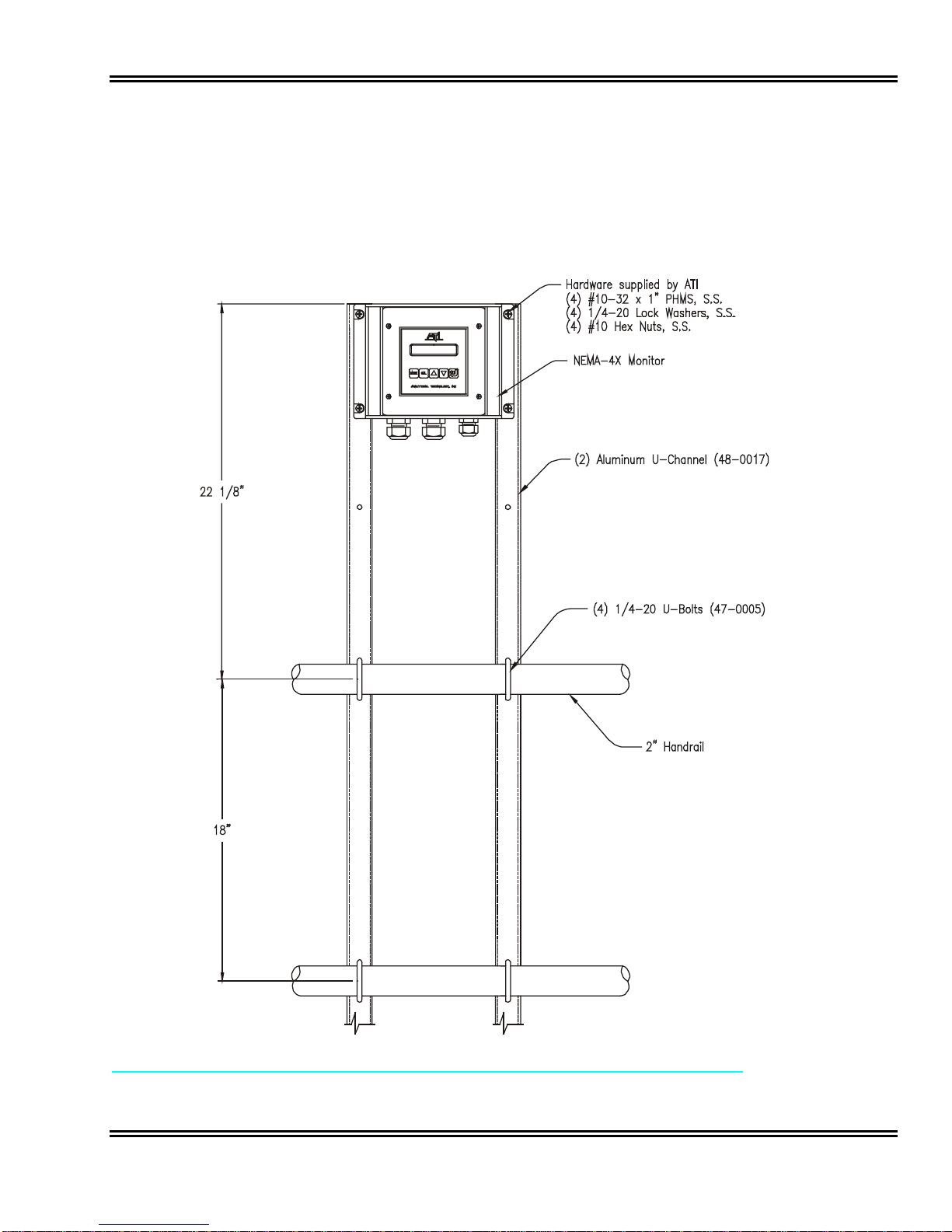
A special handrail mounting kit (part # 00-0930) is available from ATI for use on standard handrails found
around many process tanks. The mounting kit consists of two vertical aluminum supports, which are clamped to
the handrail with stainless steel u-bolts. The vertical supports are drilled for connection to horizontal handrails
with 18" center to center dimensions. If other center dimensions are encountered, new holes for the upper u-bolt
will need to be drilled. Holes at the top of the vertical supports align with the mounting feet provided on the NEMA
4X enclosure. Figure 4 shows a completely assembled handrail bracket assembly. The bracket kit includes all
necessary hardware.
FIGURE 4 - HANDRAIL MOUNTING ASSEMBLY FOR NEMA 4X ENCLOSURE (ATI-043)
Model A15/76 Turbidity Monitor
O & M Manual
Rev. E, 09/06 -10 -
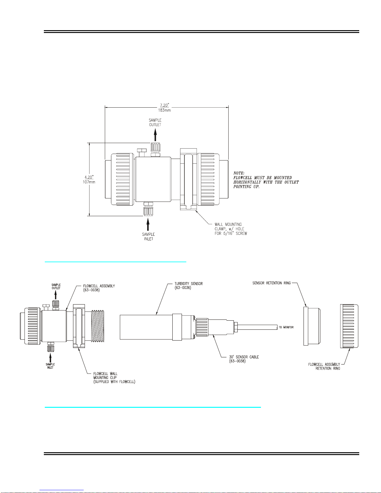
The majority of turbidity applications require the use of a flowcell assembly. This method is best when
monitoring very low turbidity values, such as filter effluent. The flowcell used with ATI’s turbidity system is
designed to eliminate ambient light effects, and to allow sample pressure to be maintained through the flowcell
minimizing air bubble formation that can cause erroneous turbidity measurements. A bracket is supplied for
mounting the flowcell to any flat surface. Figure 5 and 6 show details of the flowcell mounting. The sample outlet
must be above the sample inlet for proper operation.
FIGURE 5 FLOWCELL DIMENSIONS (ATI-0435)
FIGURE 6 EXPLODED FLOWCELL AND SENSOR ASSEMBLY (ATI-0470)
This manual suits for next models
2
Table of contents
Other Analytical Technology Measuring Instrument manuals

Analytical Technology
Analytical Technology Q46H/79PR User manual

Analytical Technology
Analytical Technology Q46F/82 User manual

Analytical Technology
Analytical Technology OL50LL User manual

Analytical Technology
Analytical Technology Q46F/D User manual

Analytical Technology
Analytical Technology Q46/85 User manual

Analytical Technology
Analytical Technology Q25R User manual

Analytical Technology
Analytical Technology Q46H/62 User manual

Analytical Technology
Analytical Technology Q46H/62-63 User manual

Analytical Technology
Analytical Technology PQ45H User manual

Analytical Technology
Analytical Technology Q45C2 User manual


