Alpha Moisture Systems DS1200-PDT User manual

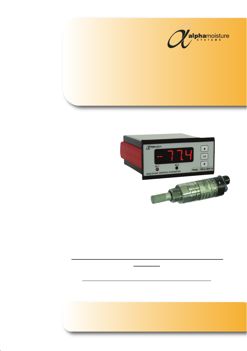
Model DS1200-PDT Dewpoint Hygrometer
-40 / +30°Cdp (50bar maximum pressure)
-60 / +20°Cdp (50bar maximum pressure)
User Manual
Englis

Model DS1200-PDT - Dewpoint Hygrometer
CERTIFICATE No. FM35600
BS EN ISO 9001:2015
Document Reference:
2249 - Issue 3
21/06/2018
Model DS1200-PDT Dewpoint Hygrometer
User Manual
©Alpha Moisture Systems Ltd.
This is a step by step instrucon manual to help you successfully set up
correctly the Model DS1200-PDT Dewpoint Hygrometer before use.
This manual should be kept with the instrument for future reference.
You must observe the safety informaon on pages 6 and 10 before
installaon.
Please read t is manual carefully from t e start.

4
Model DS1200-PDT - Dewpoint Hygrometer
Index
General Overview 5
Safety Informaon 6
Model DS1200 Control-Display Front Arrangement 7
PDT Arrangement 7
Features of the Model DS1200-PDT 7
DS1200 Mounng 8
Installing the Instrument into a Panel 8
Wiring DS1200 Power Supply 8
PDT Transmier Cable 8
Alarm Cable 9
Analogue Output Cable 9
DS1200 Connecons 9
PDT Connecons 10
Installing the Model PDT in a Air/Gas Sampling System 10-11
Piping Installaon Schemac 11-12
Installing and Commissioning the Model PDT Transmier 13
Seng the Alarm Trip Points 13
Dimensions 14
Speci caons 15-16
Contact Informaon 17

5
Model DS1200-PDT - Dewpoint Hygrometer
General Overview
Thank you for purchasing the Alp a Moisture Systems Model DS1200-PDT Dewpoint
Hygrometer.
We hope that you will agree that this instrument is easy to set up and very user friendly to
operate giving you reliable and accurate measurements quickly and efficiently.
The Model DS1200-PDT Dewpoint Hygrometer is a global popular choice of Dewpoint
Hygrometers (trace moisture analysers) that work on a basis of polymer sensors and are
used for the determinaon of moisture in most gases in the dewpoint or RH range.
They consist of a separately installed measuring cell of high grade stainless steel (available
through your local distributor or Alpha Moisture Systems where there is no distributor for
your locaon) a Transmier and Control-Display, that can be integrated in a Gas Handling
System*, and an in-line process source.
The Model DS1200-PDT Dewpoint Hygrometer is installed as a single channel analyser.
For addional accessories and parts, or technical help for the Model DS1200-PDT, or any
other Alpha Moisture Systems products, please contact your local distributor or contact
Alpha Moisture Systems - see last page for details.
*Alp a Moisture Systems can manufacture to your specificaons a Gas Sample System to
suit your exact requirements, please contact your local distributor for more informaon.
Visit our website www.amsystems.co.uk for more informaon.

6
Model DS1200-PDT - Dewpoint Hygrometer
Safety Informaon
The DS1200-PDT has been designed to be connected to hazardous electric voltages and
must be protected by a 5amp fused plug to the mains/AC supply.
Check to establish that all wiring and connecons are not damaged. If damage is
observed to any electrical wiring, connecons or damage to the apparatus they must not
be connected to the mains/AC supply but returned to your local distributor for rec caon.
Warnings
Risk of electric shock - Do not open any part of the enclosures of the Model DS1200-PDT
whilst connected to the mains/AC supply.
Do not connect the Model DS1200-PDT to the mains/AC supply unl all other connecons
and pipework is secure and have been tested.
Ignoring this safety informaon could result in severe personal injury and/or mechanical
damage to the Model DS1200-PDT.
The product speci caons must not be exceeded at anyme, as this may cause personal
injury, damage to the instrument and sensor or cause risk of re.
Do not connect the Model DS1200-PDT to any other device that is not recommended in
this manual.
Ensure that the Model DS1200-PDT does not come into direct contact with water or any
other liquids. See IP/NEMA protecon in the product speci caons.
To avoid the risk of electric shock, risk of damage or re, these safety instrucons and
guidelines must be followed. Only quali ed personnel/technicians should install these
units to the mains/AC supply and connecng pipework to ensure it is completely safe by
tesng and recording before use.
It is the responsibility of the customer to ensure safe working condions especially working
with hazardous gases and liquids. Leak tests should be carried out periodically by quali ed
personnel.
Safe Isolaon
Switch off at the mains/AC socket and remove the plugs before any maintenance is carried
out by a quali ed person. Always test components with an approved voltage meter before
handling to ensure it is completely dead.
YOU MUST ALSO READ THE WARNING INFORMATION ON PAGE 10.
7
Model DS1200-PDT - Dewpoint Hygrometer
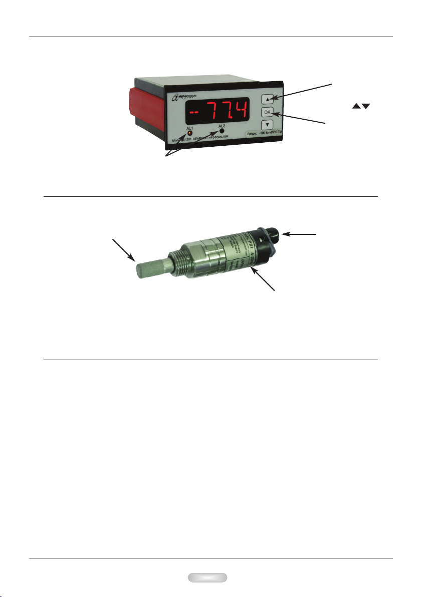
Model DS1200 Control-Display Front Arrangement
LED Alarm Indicators. Sounders
can also be connected at the rear
of the unit. See page 9 diagram.
Menu
navigaon
keys
Con rmaon
key
PDT Transmier Arrangement
See Pages 14 - 16 for dimensions, diagrams and tec nical specificaons
Permeable
Sensor Guard
SUPPLIED WITH A CERTIFICATE OF CALIBRATION
Iden caon Label
with Serial Number
Cable
Connecon
Features of t e Model DS1200-PDT
DS1200 Control-Display
• The Model DS1200-PDT is a single channel analyser.
• DS1200 has a 4-digit 14 segment LED display
• DS1200 has 2 adjustable Alarm set points and an analogue output. See pages 9 and 13.
• DS1200 has mA Output (terminals 11 and 12)
• Universal Voltage Supply (terminals 31 & 32)
PDT Transmier
• Ranges available: -40 to +30°C or -60 to +20°C (-40 to +86°F or -76 to +68°F) Dewpoint
• Two wire 4-20mA transmier for connuous measurement of moisture in a process
gas or compressed air
• Reliable, accurate and easy to install

8
Model DS1200-PDT - Dewpoint Hygrometer
DS1200 Mounng
• Only technicians who are familiar with the technical terms, warnings, and instrucons
in the manual and who are able to follow these should connect the DS1200.
• Should there be any doubt as to the correct handling of the DS1200, please contact
your local distributor.
• Mounng and connecon of the DS1200 should comply with the naonal legislaon
for the mounng of electric materials, i.e. wire cross-secon, protecve fuse, and
locaon.
Descripons of Input / Output and supply connecons are shown in the block diagram
on page 9 and the instrument top label.
• The maximum size of the protecve fuse is 5A and, together with the power switch, it
should be easily accessible and close to the DS1200. The power switch should be
marked with a label indicang it will turn OFF the voltage to the DS1200.
• To be mounted in front panels. The included rubber packing must be mounted between
the panel cutout and the display front to obtain IP65 (NEMA 4) ingress protecon.
Installing t e Instrument into a Panel
• Make a cut-out in the donor panel 92.0/92.8 x 45.0/45.6mm (DIN 43700).
• The maximum panel thickness is 10mm and, if an effecve IP65 weatherproof seal is
required, the minimum recommended panel thickness is 1.6mm.
• Pass the instrument cabinet through the cut-out in the donor panel and slide the panel
clamp over the instrument, from the back.
• Turn the Red panel clamp screws unl the instrument is clamped in posion. The
screws must be ghtened sufficiently to affect a seal between the front of the donor
panel and the back of the instrument bezel, but never over ghtened to the point of
fracturing the panel clamp or instrument case.
NOTE Wires are retained by screws. Ensure t at t e exposed secon of t e wire is fully
inserted and t at no loose strands are exposed.
Wiring DS1200 Power Supply
• Connect the power supply cable to the 2 terminal block marked 31 and 32 no polarity.
• The power supply should be 22 to 253 VAC @ 50/60Hz or 20 to 300 VDC.
PDT Transmier Cable
• Connect the transmier cable to connector pins 45 and 46, ensuring that the red wire
connects to pin 46. See Diagrams on pages 9 and 10.
Observe that the cage is securely clamped onto the bootlace ferrules on the cable
provided.
• Route the sensor cable to the intended site of the sensor.
Note : - Do not install t e transmier at t is me.
Wait unl t e commissioning stage as described later

9
Model DS1200-PDT - Dewpoint Hygrometer
Alarm Cable
• Make the appropriate connecons, nong the normally open and normally closed relay
contact posions.
Analogue Output Cable
• Make the appropriate connecons, ensuring that the correct polarity and the
maximum load speci caon is strictly observed.
DS1200 Connecons:
BLUE wire from the
PDT Cable connected
to pin 45 on the rear
of DS1200
RED wire from the
PDT Cable connected
to pin 46 on the rear
of DS1200
Polarity is universal
and can be wired +/-
or -/+
10
Model DS1200-PDT - Dewpoint Hygrometer
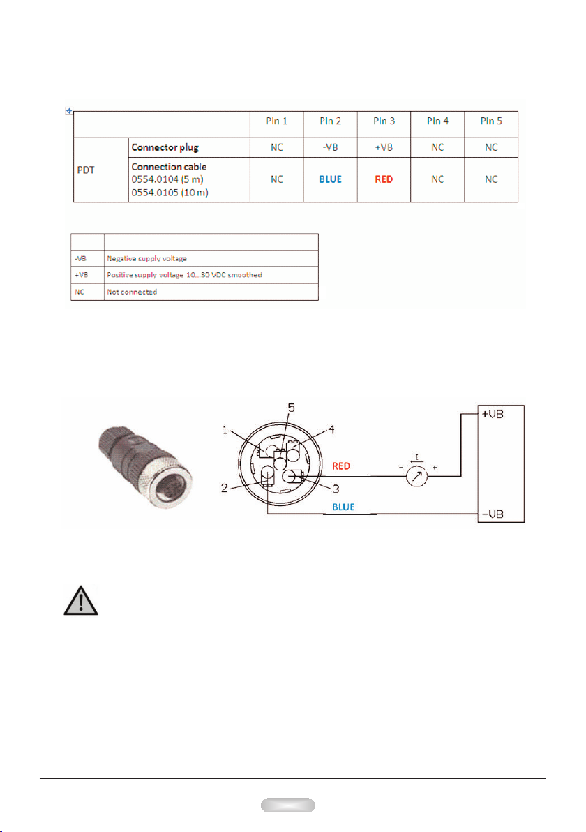
M12 connector plug
If no connecon cable is ordered, the sensor will be supplied with a M12 connector plug.
The user can connect the supply and signal cables as indicated in the connecon diagram
below.
PDT Connecons:
Pin 2 to Pin 45 on
DS1200
Pin 3 to Pin 46 on
DS1200
Installing t e Model PDT in a Air/Gas Sampling System
Warning: D n t exceed a pressure f 50 bar.
Observe the o erating ranges of the sensor. The robes are damaged if they are
overheated.
Observe maximum storage and trans ort tem erature as well as maximum
o erating tem erature (i.e. rotect the instrument from direct sunlight).
Imp rtant: Before installation, bleed com ressed air systems in order to remove
condensate and articles to avoid contamination.
Table of contents
Other Alpha Moisture Systems Measuring Instrument manuals

Alpha Moisture Systems
Alpha Moisture Systems dewSMART DS1000 User manual

Alpha Moisture Systems
Alpha Moisture Systems SADPmini2 User manual

Alpha Moisture Systems
Alpha Moisture Systems SADPminiEx User manual

Alpha Moisture Systems
Alpha Moisture Systems DS1200-AMT Guide

Alpha Moisture Systems
Alpha Moisture Systems dewTEC DS2000 User manual

Alpha Moisture Systems
Alpha Moisture Systems SADPmini2 User manual


