AgSense Crop Link Lite User manual

WIRING INSTRUCTIONS
2017-18
Crop Link Lite/Pro
TANK MONITORING

Items Covered In This Manual:
Page 1: Crop Link Device Overview
Page 2: Connecting DC Power/Solar Panel
Page 3: Connecting 120v AC Power
Page 4: Connecting the Tank Monitor Sensor
Page 5: Sensor Installation Tips
Page 6-7: Submersible Tank Monitor Sensor
Page 8-9: Specs and Warranty Information

General Overview of the Crop Link Unit
Note: Once all sensors are connected and unit is ready to run, contact your AgSense Dealer to
finish setup, and configure this unit to read the sensors that you have installed. Page 1

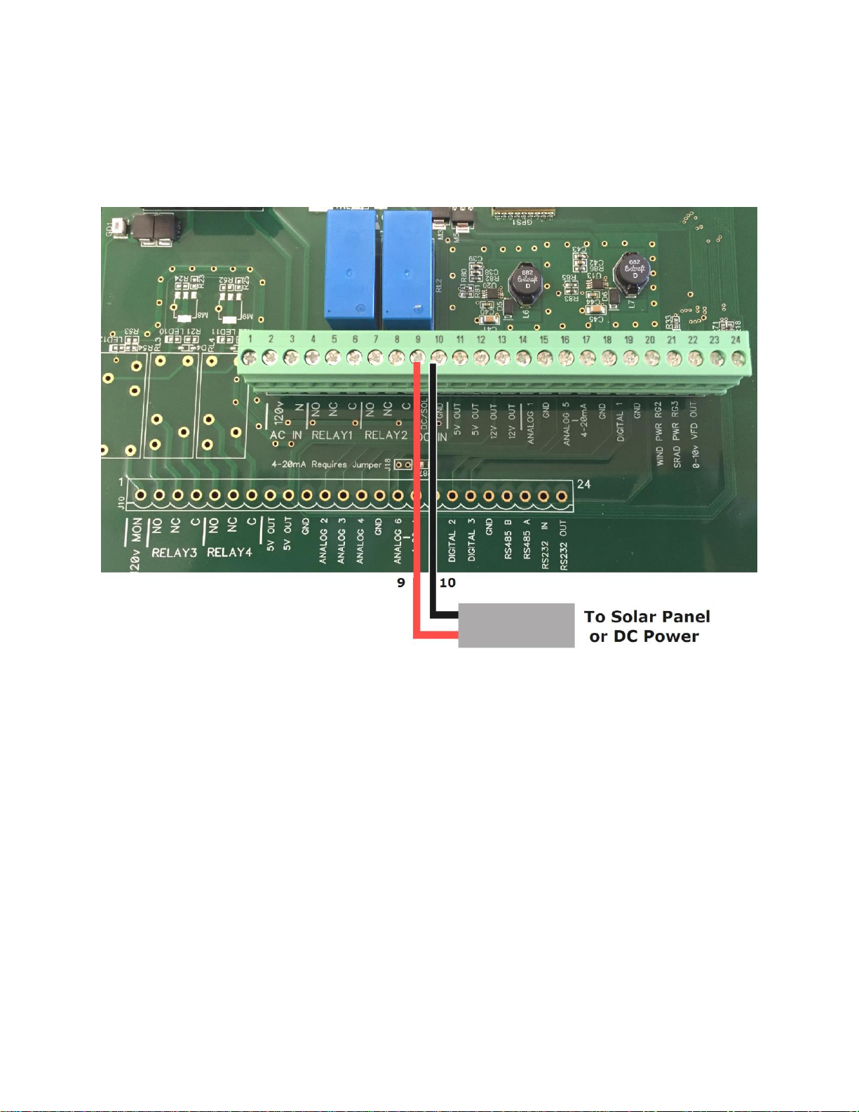
Wiring the DC Power or Solar Panel to the
Crop Link Unit
Wiring the solar panel or 7-30v DC power Source: Find the last two terminals on the large
terminal strip labeled DC/SOL and GND
1. Connect the Black or Negative Wire (-) from the solar panel to the terminal marked GND
as shown above.
2. Connect the Red or Positive Wire (+) from the solar panel to the terminal marked
DC/SOL as shown above.
Page 2

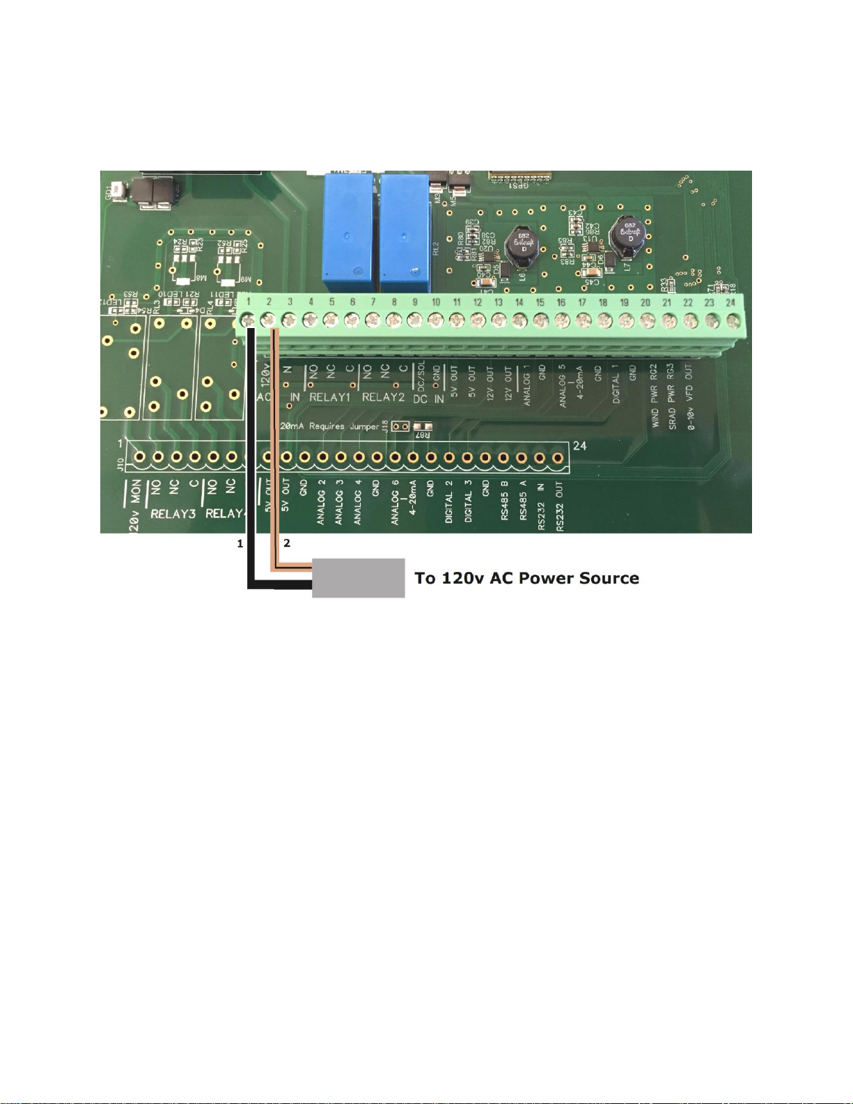
Wiring 120v AC Power to the Crop Link Unit
If you are not using DC power or Solar Power: how to wire 120v AC to the Crop Link.
1. Connect 120v AC to the terminal marked 120v –units pre-wired with a cable from
AgSense use a Black wire. Cable added by the customer should use the Black wire
here.
2. Connect the Neutral wire to the terminal marked N. –units pre-wired with cables
from AgSense use either a Brown/Black Stripe or a White wire. Cable added by the
customer should use the white wire.
Page 3

Wiring the G3 Tank Monitor sensor
to the Crop Link Unit
1. Connect the Red wire from the Tank Monitor Sensor to the terminal marked 12V
OUT as shown above.
2. Connect the Black wire from the Tank Monitor Sensor to any terminal marked GND
as shown above.
3. Connect the White wire from the Tank Monitor Sensor to the terminal marked AN1
as shown above.
Note: Repeat steps 1-2 for a second Tank Monitor sensor, but connect the White wire to AN2
instead.
Page 4

Tank Monitor Sensor Installation Tips:
1. Sensors have an accuracy of +/- 3”
2. Sensor should be installed on the outside of the tank, as close to the bottom of the tank as
possible, but not below the bottom of the tank. (typical locations would be just after the
output flange, or T’ed into the bottom of the sight tube) The sensor will not be able to
read any changes in level below the sensor.
3. You must install a ball valve in-line before the tank monitor sensor in case of any sensor
leak or failure that would require the removal/replacement of the sensor.
4. Tank Monitor sensors should not be used in clumpy/sludge/sewage/manure liquids due to
the possibility of clogging the sensor opening with course/foreign matter.
5. When using multiple tank monitor sensors, most installs will have a max of 2 sensors.
The two sensors should be installed in adjacent tanks, with the Crop Link mounted
between those two tanks, positioned for the best view of the sun for the most amount of
hours. (if using a solar panel) - One mounting style is a 55 gallon barrel (plastic or steel)
filled with dirt/gravel, with a tee post installed into the dirt/gravel, then use a beam clamp
to attach the unit directly to the tee post. –the other method of mounting would be any
metal bracket built by the user that allows the cables to reach the Crop Link and gives the
solar panel the most amount of sunlight possible (if using a solar panel)
6. Caution - This transducer, while resembling our water pressure
transducer, should NOT be used on a pivot. Doing so could result in the
sensor being permanently damaged.
Remember to Configure the Tank Monitor Sensor on the AgSense
Website when installation is complete.
Page 5

Submersible Tank Level Sensor Wiring:
Ashcroft KM45 series
1. Install the White wire into the 12v Out terminal as shown above.
2. Install the Brown wire into the GND terminal as shown above
3. Install the Yellow wire into any input (AN1 to AN4) terminal as shown above.
4. Green wire is not used and can be capped off.
Note: DO NOT shorten or lengthen the cable on this transducer. This cable contains an air vent
tube and filter that is critical to this transducer functioning correctly –do not modify!!
Page 6

Submersible Tank Level Sensor Wiring:
Ashcroft SL17 series 4-20mA sensor
1. Install the Red wire into the 12v Out terminal as shown above.
2. Install the Green and Bare wires into the GND terminal as shown above
3. Install the Black wire into input AN5 4-20mA or AN6 4-20mA terminal as shown above.
4. White wire is not used and can be capped off.
5. Make sure a jumper is installed as shown above or the 4-20mA input will not work.
Note: DO NOT shorten or lengthen the cable on this transducer. This cable contains an air vent
tube and filter that is critical to this transducer functioning correctly –do not modify!!
Page 7

Power Requirements for the Crop Link unit:
SOLAR/DC Powered Unit 7-34V DC:
At 12v DC: 1.0A MAX
0.1A - 0.5A during normal operation
Recommended Solar panel –Must be a minimum of 10 watt @ 17v Solar panel.
Specs of solar panels that ship from AgSense:
10 watt
Operating Voltage 17v DC
Operating Current 0.59A
Open Circuit Voltage 21.2v DC
Short Circuit Current 0.69A
Warranty Information:
All warranty service provided by the AgSense service center, or an authorized technician.
Warranty repairs require a Return Merchandise Authorization Number (RMA);
Have your dealer contact AgSense to obtain this RMA number.
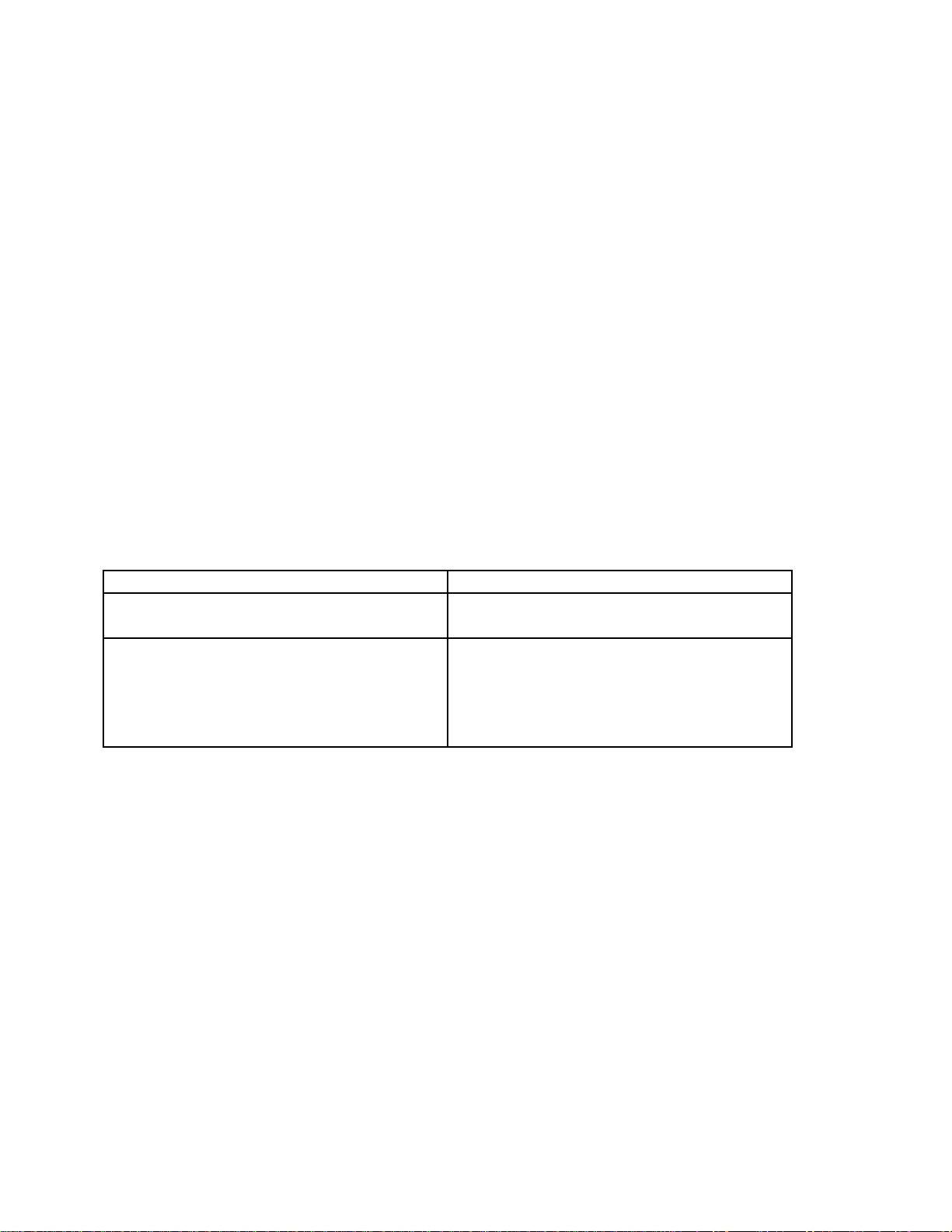
For the Period of :
AgSense will:
60 Days
Money back Guarantee if not satisfied with
product.
2 Years
Repair on any unit that fails due to defect
in materials or workmanship. AgSense
labor and parts would be provided free of
charge during the warranty period. (This
does not include dealer labor.)
What is not covered:
Service trips to your home to teach you how to use the product.
Improper installation, delivery or maintenance. If you have an installation problem contact your
dealer or installer.
Failure of product resulting from modification to product or due to unreasonable failure to provide
reasonable and necessary maintenance.
Labor necessary to move device from one location to another.
Improper installation of battery.
Failure due to corrosion or water damage.
oUnits installed in direct contact with sprinklers require a tower box or other watertight
protection.
Damage to the product caused by improper power supply voltage, accident, fire, floods or acts of
God.
Damage caused after delivery.
Page 8
Other manuals for Crop Link Lite
1
This manual suits for next models
1
Other AgSense Measuring Instrument manuals