AAT MEGA II CLEANER User manual

MEGA II CLEANER
Rev 2.0
10/15/2005
OPERATING MANUAL
Austin American Technology Corporation
12201 Technology Blvd., Suite 160
Austin, Texas 78727-6102
Tel (512) 335-6400 Fax (512) 335-5753
Web site address: www.aat-corp.com

Copyright © 1984, 2005 Austin American Technology Corporation. All Rights Reserved.
Mega is a registered trademark of Austin American Technology Corporation. MegaSolv is a trademark of
Austin American Technology Corporation
Printed in U.S.A.
Foreign and U.S. Products of Austin American Technology Corporation are covered by Foreign and U.S.
patent or patents pending. No part of this Publication may be translated and/or reproduced or stored in a
data retrieval system, or transmitted in any form or by any means without the express written permission
of Austin American Technology Corporation. Information in this publication supersedes all previously
published material. Specification and price change privileges reserved.
All of the information contained herein is, to the best of our knowledge, correct. Users, however, should
independently evaluate the suitability of each product for their application. Austin American Technology
Corporation, makes no warranties as to the accuracy or the completeness of the information, and
disclaims any liability regarding its use.

Mega II Operating Manual Rev. 2.0 10/15/2005 i
Table of Contents
1.0 OPERATOR SAFETY SUMMARY
1.1 Symbols on the Equipment ............................................................................. 2
1.2 Additional Precautions .................................................................................... 3
1.3 MEGA II Safety Features ................................................................................ 4
2.0 INSTALLATION AND SET UP
2.1 Introduction ..................................................................................................... 5
2.2 Installation/Set Up ........................................................................................... 6
2.3 System Components ...................................................................................... 8
3.0 THE CLEANING PROCESS
3.1 Final Cleaning Cycle ..................................................................................... 13
4.0 OPERATOR INTERFACE
4.1 Using the Operator Interface ........................................................................ 15
4.2 Menu Modes ................................................................................................. 15
4.2.1 Menu Mode ............................................................................................ 15
4.2.2 Non-Menu Mode..................................................................................... 15
4.3 Entering/Changing Settings .......................................................................... 16
4.4 Menu Structure ............................................................................................. 17
5.0 OPERATION
5.1 Starting and Stopping the System ................................................................ 21
5.2 Menu Selections ........................................................................................... 21
5.2.1 Initiate Cycle 1-5..................................................................................... 21
5.2.2 View System Settings............................................................................. 22
5.2.3 View Cycle Setup ................................................................................... 22
5.2.4 View IAC Saturation ............................................................................... 22
5.2.5 View IAC Run Time ................................................................................ 23
5.2.6 View Cycle Count ................................................................................... 23
5.2.7 Change Cycle Setup 1-5 ........................................................................ 23
5.3 Maintenance Menu ....................................................................................... 25
5.3.1 Fill System Hold Tank ............................................................................ 25
5.3.2 Drain System Hold Tank ........................................................................ 25
5.3.3 System/Chem. Cleanup ......................................................................... 25
5.3.4 Rinse Drain Time.................................................................................... 25
5.3.5 Change IAC Saturation Time ................................................................. 26
5.3.6 Reset IAC Run Time .............................................................................. 26
5.3.7 Reset Cycle Counter .............................................................................. 26
5.3.8 Cycle Counter Lockout........................................................................... 26
5.3.9 Analog Conversion ................................................................................. 26
5.3.10 Enable/Set Password ............................................................................. 27

ii Rev. 2.0 10/15/2005 Mega II Operating Manual
6.0 PREVENTIVE MAINTENANCE
7.0 PARAMETERS FOR RESISTIVITY CONTROLLER
7.1 Mega II Cleaner: Wash-MegaSolv JB ........................................................... 31
7.1.1 Outputs................................................................................................... 31
7.1.2 Menus..................................................................................................... 31
8.0 PARAMETERS FOR RESISTIVITY CONTROLLER (RC1)
8.1 Mega II Cleaner: Wash-Water ...................................................................... 33
8.1.1 Outputs................................................................................................... 33
8.1.2 Menus..................................................................................................... 33
8.2 Recirculating Heater System Only ................................................................ 33
9.0 REPLACEMENT/SPARE PARTS
APPENDIX A SCHEMATICS
APPENDIX B OPTIONS
B.1 PURGE AND PRESSURIZATION OPTION ................................................ 51
B.1.1 Initial System Power 52
B.1.2 Post Start-Up Power 52
B.2 RECIRCULATION HEATER SYSTEM OPTION ......................................... 52
B.2.1 Operation 52
B.3 PREWASH / SOAK OPTION ....................................................................... 54
B.3.1 Solution Cross Over 55
B.3.2 Change Cycle Setup 1-5 58
B.3.3 PREWASH CYCLE 59
B.4 OPEN LOOP RINSE OPTION ..................................................................... 60
B.4.1 OPEN LOOP RINSE CYCLE 62
B.5 DATA LOGGING PROGRAM OPTION ...................................................... 63
B.5.1 200CR CONTROLLER PROGRAM- Help Files 64
B.5.2 Communications Port Setup 65
B.5.3 200CR Meter 67
B.6 ULTRASONICS CLEANING OPTION ......................................................... 67
B.6.1 Specifications 68
B.6.2 Change Cycle Setup 1-5 69
B.7 CHILLER ...................................................................................................... 70
B.8 COOLING COILS ........................................................................................ 74
APPENDIX C TERMS AND CONDITIONS

Mega II Operating Manual Rev. 2.0 10/15/2005 iii
List of Figures
Figure 1. Symbols on Equipment ............................................................................. 2
Figure 2. Installation ................................................................................................. 7
Figure 3. System Components ................................................................................. 9
Figure 4. Operator Interface Flow Chart ................................................................. 19
Figure B-1. 200CR Control Panel .............................................................................. 67
Figure B-2. Chiller ...................................................................................................... 70
Figure B-3. Chiller Option Airflow Direction ................................................................ 71
Figure B-4. Chiller Connections ................................................................................. 71
Figure B-5. Chiller Connections ................................................................................. 72
Figure B-6. Chiller Plumbing Connections ................................................................. 73
Figure B-7. Holding Tank and Cooling Coils .............................................................. 74
Figure B-8. Plumbing Connections for Cooling Coils ................................................. 75
Figure B-9. Cooling Coils in Hold Tank ...................................................................... 75

iv Rev. 2.0 10/15/2005 Mega II Operating Manual

Mega II Operating Manual Rev. 2.0 10/15/2005 v
List of Tables
Table 1. Available Phases ..................................................................................... 11
Table 2. Sequence of Events ................................................................................ 13
Table 3. Menu Selections ...................................................................................... 17
Table 4. Menu Structure ........................................................................................ 18
Table 5. Key Press Sequence to Run a Cycle ...................................................... 22
Table 6. Cycle Change Key Press Sequence ....................................................... 23
Table 7. Cleanup Function Key Selections ........................................................... 25
Table 8. Analog Conversions ................................................................................ 26
Table 9. Key Selections to Set the Password ....................................................... 27
Table 10. Spare Parts List ....................................................................................... 35

vi Rev. 2.0 10/15/2005 Mega II Operating Manual

Mega II Operating Manual Rev. 2.0 10/15/2005 1
1.0 OPERATOR SAFETY SUMMARY
The safety information in this summary is for the benefit of operating personnel.
Warnings and Cautions will also be found throughout the manual where they
apply.
Terms in This Manual
CAUTION statements identify conditions or practices that could result in
damage to the equipment or to other property.
WARNING statements identify conditions or practices that could result in
personal injury or loss of life.
Properly Install the Equipment
For safe operation, this equipment must be properly installed, following the
instructions in the INSTALLATION section of this manual.
Protectively Ground the Equipment
For electric-shock protection, this product must be protectively grounded as
part of the installation procedure. Use the green/yellow grounding conductor
provided for this purpose.
Connect to Earth-Referenced Power System Only
Note: This equipment must only be powered by a single-phase earth-
referenced power source in which the potential power never exceeds
240 volts.
Note: This equipment must never be connected to an “IT” power system with
an impedant neutral connection. During a supply system fault
condition, the equipment insulation system could be over-stressed,
creating an electric-shock hazard.
2 Rev. 2.0 10/15/2005 Mega II Operating Manual
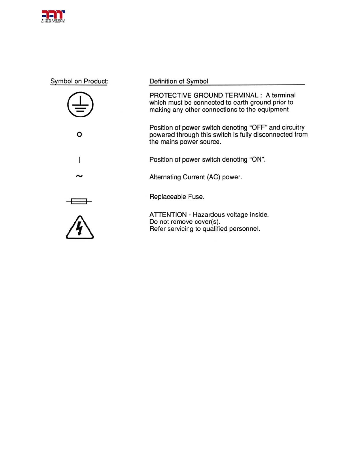
1.1 SYMBOLS ON THE EQUIPMENT
The definition of each symbol used on the Cleaning System is as follows:
Figure 1. Symbols on Equipment
CAUTION and WARNING Notices on the Equipment
The following notices, together with additional explanatory information, address
hazards associated with improper use of the equipment.
CAUTION - DO NOT SIT, STAND, LEAN, OR APPLY EXCESSIVE WEIGHT TO
THE OPEN DOOR.
The door of the equipment is only intended to support the wash rack and its
contents. Overloading the door mounting hardware will damage the equipment,
resulting in improper door operation and the potential for water leaks. Severely
overloading the open door could also cause the equipment to tip over, resulting
in substantial damage and possibly personal injury.
WARNING - RISK OF FIRE. USE ONLY APPROVED SOLVENTS.
This equipment is designed primarily to use water and saponifier as the
cleaning agent. Addition or substitution of other cleaning agents, especially
liquids classed as FLAMMABLE, could result in fire or explosion. Incompatible
Table of contents


