Vega VEGAFLEX 81 User manual
Quick setup guide
TDR sensor for continuous level and
interface measurement of liquids
VEGAFLEX 81
Foundation Fieldbus
Rod and cable probe
Document ID: 47589

2
Contents
VEGAFLEX 81 • Foundation Fieldbus
47589-EN-140324
Contents
1 For your safety
1.1 Authorised personnel ....................................................................................................... 3
1.2 Appropriate use................................................................................................................ 3
1.3 Warning about incorrect use............................................................................................. 3
1.4 General safety instructions............................................................................................... 3
1.5 CE conformity................................................................................................................... 3
1.6 NAMUR recommendations .............................................................................................. 4
1.7 Environmental instructions ............................................................................................... 4
2 Product description
2.1 Conguration.................................................................................................................... 5
3 Mounting
3.1 General instructions for use of the instrument .................................................................. 7
3.2 Mounting instructions ....................................................................................................... 7
4 Connecting to power supply
4.1 Connecting..................................................................................................................... 10
4.2 Wiring plan, single chamber housing.............................................................................. 11
4.3 Wiring plan, double chamber housing ............................................................................ 12
5 Set up with the display and adjustment module
5.1 Insert display and adjustment module............................................................................ 13
5.2 Parameter adjustment - Quick setup .............................................................................. 14
6 Supplement
6.1 Technical data ................................................................................................................ 17
Information:
This quick setup guide enables a quick setup of your instrument.
Youcanndfurtherinformationinthecorresponding,comprehensive
operating instructions. This manual is available on the supplied DVD
or in the download area under "www.vega.com".
Operating instructions VEGAFLEX 81 - Foundation Fieldbus -
Rod and cable probe: Document-ID 44218
Editing status of the quick setup guide: 2014-03-17

3
1 For your safety
VEGAFLEX 81 • Foundation Fieldbus
47589-EN-140324
1 For your safety
1.1 Authorised personnel
All operations described in this operating instructions manual must
be carried out only by trained specialist personnel authorised by the
plant operator.
During work on and with the device the required personal protective
equipment must always be worn.
1.2 Appropriate use
VEGAFLEX 81 is a sensor for continuous level measurement.
Youcannddetailedinformationabouttheareaofapplicationin
chapter "Product description".
Operational reliability is ensured only if the instrument is properly
usedaccordingtothespecicationsintheoperatinginstructions
manual as well as possible supplementary instructions.
1.3 Warning about incorrect use
Inappropriate or incorrect use of the instrument can give rise to
application-specichazards,e.g.vesseloverllordamagetosystem
components through incorrect mounting or adjustment.
1.4 General safety instructions
This is a state-of-the-art instrument complying with all prevailing
regulations and guidelines. The instrument must only be operated in a
technicallyawlessandreliablecondition.Theoperatorisresponsible
for the trouble-free operation of the instrument.
During the entire duration of use, the user is obliged to determine the
compliance of the necessary occupational safety measures with the
current valid rules and regulations and also take note of new regula-
tions.
The safety instructions in this operating instructions manual, the na-
tional installation standards as well as the valid safety regulations and
accident prevention rules must be observed by the user.
For safety and warranty reasons, any invasive work on the device
beyond that described in the operating instructions manual may be
carried out only by personnel authorised by the manufacturer. Arbi-
traryconversionsormodicationsareexplicitlyforbidden.
The safety approval markings and safety tips on the device must also
be observed.
1.5 CE conformity
ThedevicefulllsthelegalrequirementsoftheapplicableECguide-
lines.ByaxingtheCEmarking,weconrmsuccessfultestingofthe
product.
YoucanndtheCECerticateofConformityinthedownloadsection
of our homepage.

4
1 For your safety
VEGAFLEX 81 • Foundation Fieldbus
47589-EN-140324
Electromagnetic compatibility
Instrumentsinfour-wireorEx-d-iaversionaredesignedforuseinan
industrial environment. Nevertheless, electromagnetic interference
from electrical conductors and radiated emissions must be taken into
account, as is usual with class A instruments according to EN 61326-
1.Iftheinstrumentisusedinadierentenvironment,theelectromag-
netic compatibility to other instruments must be ensured by suitable
measures.
1.6 NAMUR recommendations
NAMUR is the automation technology user association in the process
industry in Germany.The published NAMUR recommendations are
acceptedasthestandardineldinstrumentation.
ThedevicefulllstherequirementsofthefollowingNAMURrecom-
mendations:
• NE 21 – Electromagnetic compatibility of equipment
• NE 43 – Signal level for malfunction information from measuring
transducers
• NE53–Compatibilityofelddevicesanddisplay/adjustment
components
• NE107–Self-monitoringanddiagnosisofelddevices
For further information see www.namur.de.
1.7 Environmental instructions
Protection of the environment is one of our most important duties.
That is why we have introduced an environment management system
with the goal of continuously improving company environmental pro-
tection.Theenvironmentmanagementsystemiscertiedaccording
to DIN EN ISO 14001.
Pleasehelpusfulllthisobligationbyobservingtheenvironmental
instructions in this manual:
• Chapter "Packaging, transport and storage"
• Chapter "Disposal"
5
2 Product description
VEGAFLEX 81 • Foundation Fieldbus
47589-EN-140324
2 Product description
2.1 Conguration
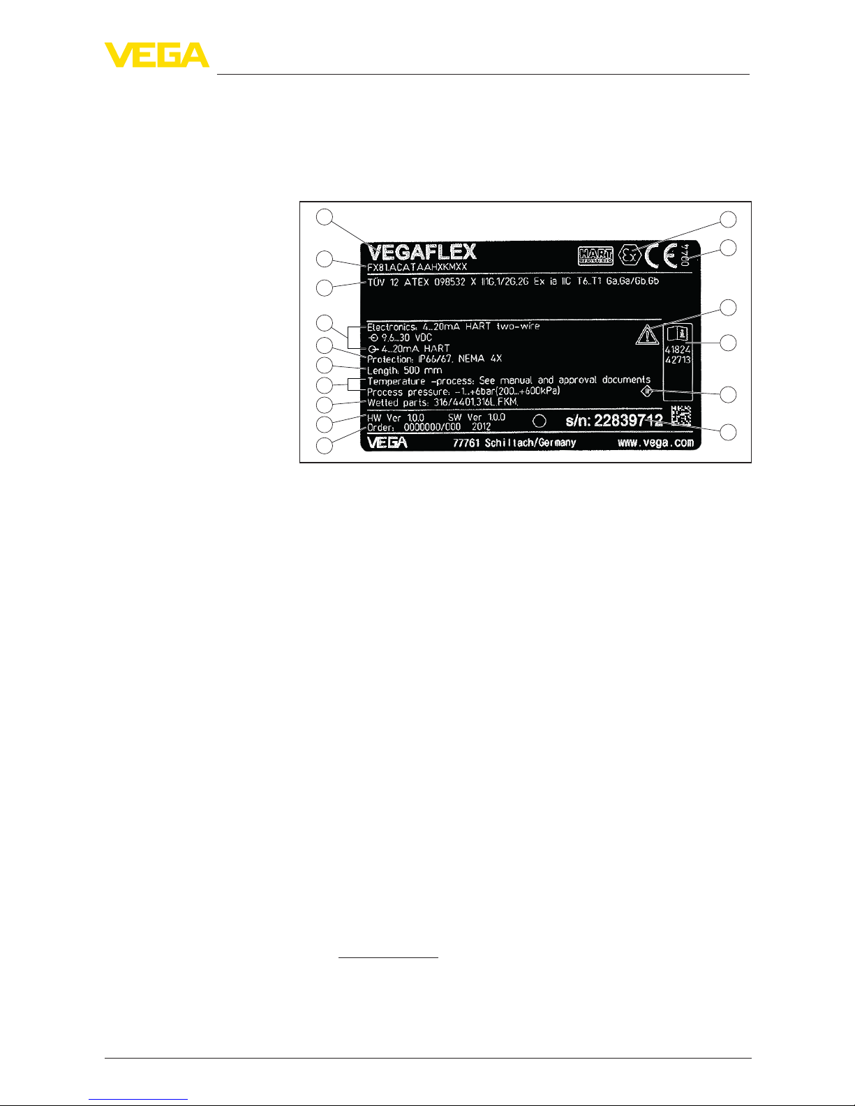
Thetypelabelcontainsthemostimportantdataforidenticationand
use of the instrument:
2
1
13
14
15
16
12
11
5
3
6
4
7
8
9
10
Fig. 1: Layout of the type label (example)
1 Instrument type
2 Product code
3 Approvals
4 Power supply and signal output, electronics
5 Protection rating
6 Probe length
7 Process and ambient temperature, process pressure
8 Material, wetted parts
9 Hardware and software version
10 Order number
11 Serial number of the instrument
12 Symbol of the device protection class
13 ID numbers, instrument documentation
14 Reminder to observe the instrument documentation
15 NotiedauthorityforCEmarking
16 Approval directives
The type label contains the serial number of the instrument. With it
youcanndthefollowinginstrumentdataonourhomepage:
• Product code (HTML)
• Delivery date (HTML)
• Order-specicinstrumentfeatures(HTML)
• Operating instructions and quick setup guide at the time of ship-
ment (PDF)
• Order-specicsensordataforanelectronicsexchange(XML)
• Testcerticate(PDF)-optional
Go to www.vega.com, "VEGATools" and "Instrument search". Enter
the serial number.
Alternatively, you can access the data via your smartphone:
• Download the smartphone app "VEGATools" from the "Apple App
Store" or the "GooglePlayStore"
Type label
Serial number - Instru-
ment search

6
2 Product description
VEGAFLEX 81 • Foundation Fieldbus
47589-EN-140324
• ScantheDataMatrixcodeonthetypelabeloftheinstrumentor
• Enter the serial number manually in the app
7
3 Mounting
VEGAFLEX 81 • Foundation Fieldbus
47589-EN-140324
3 Mounting
3.1 General instructions for use of the instrument
Protect your instrument against moisture penetration through the fol-
lowing measures:
• Use the recommended cable (see chapter "Connectingtopower
supply")
• Tighten the cable gland
• Turn the housing in such a way that the cable gland points down-
ward
• Loop the connection cable downward in front of the cable gland
This applies particularly to:
• Outdoor mounting
• Installationsinareaswherehighhumidityisexpected(e.g.through
cleaning processes)
• Installations on cooled or heated vessels
3.2 Mounting instructions
Mount VEGAFLEX 81 in such a way that the distance to vessel instal-
lations or to the vessel wall is at least 300 mm (12 in). In non-metallic
vessels, the distance to the vessel wall should be at least 500 mm
(19.7 in).
During operation, the probe must not touch any installations or the
vessel wall. If necessary, fasten the probe end.
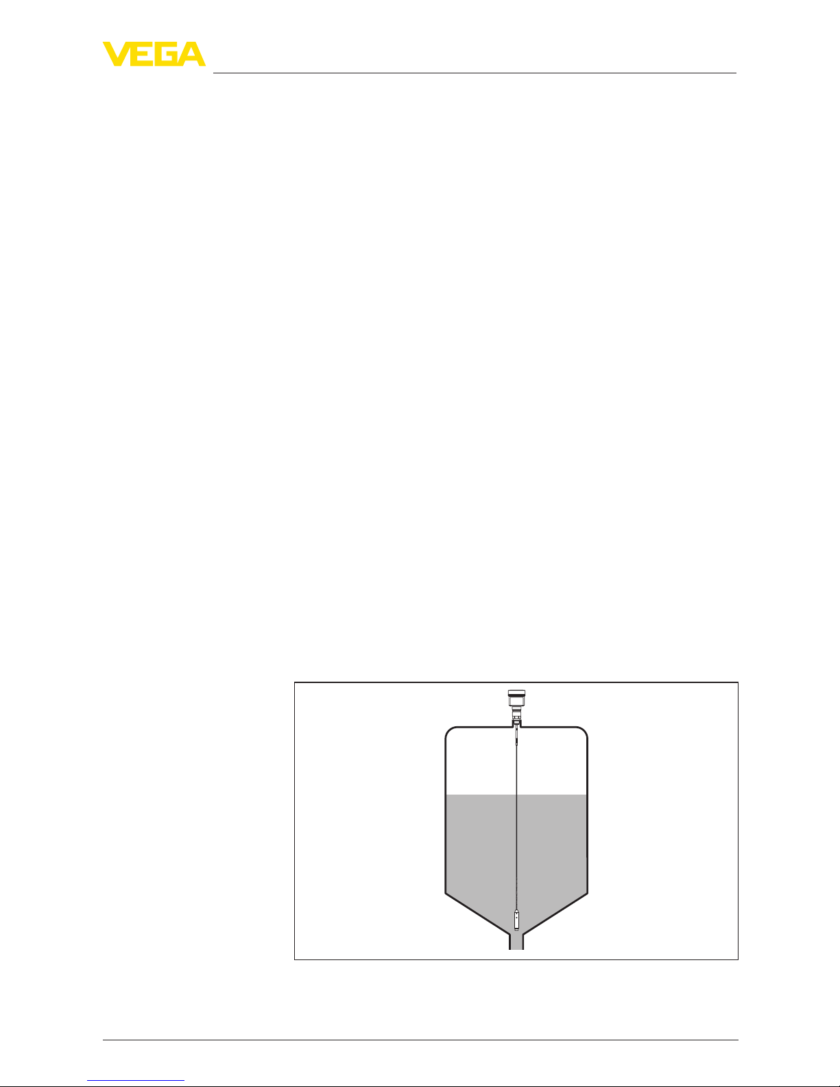
In vessels with conical bottom it can be advantageous to mount the
sensor in the center of the vessel, as measurement is then possible
nearly down to the lowest point of the bottom. Keep in mind that
measurement all the way down to the tip of the probe may not be pos-
sible.Theexactvalueofthemin.distance(lowerdeadband)isstated
in chapter "Technicaldata".
Fig. 2: Vessel with conical bottom
Protection against mois-
ture
Installation position
8
3 Mounting
VEGAFLEX 81 • Foundation Fieldbus
47589-EN-140324
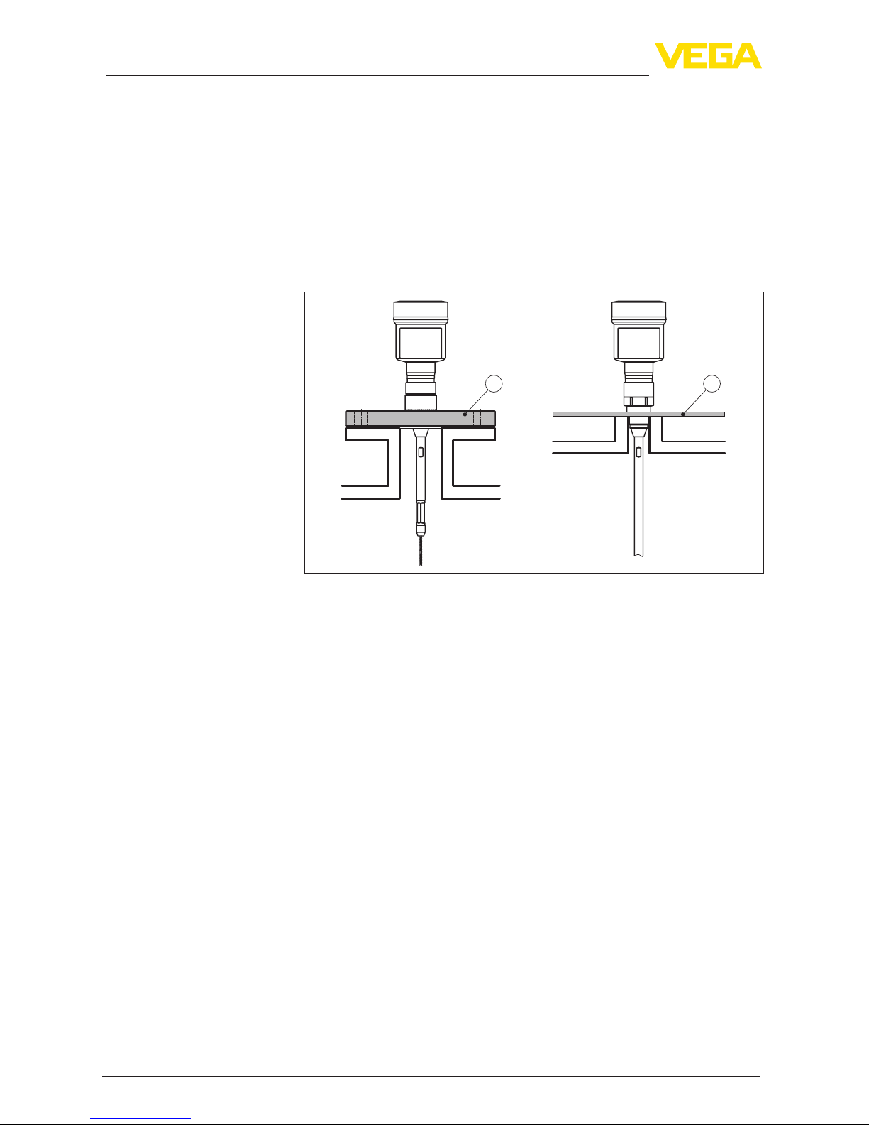
Plastic vessel/Glass vessel
The guided microwave principle requires a metallic surface on the
processtting.Therefore,inplasticvessels,etc.,useaninstru-
mentversionwithange(fromDN50)orplaceametalsheet
(ø>200mm/8in)beneaththeprocessttingwhenscrewingitin.
Makesurethattheplatehasdirectcontactwiththeprocesstting.
When installing rod or cable probes in vessels without metal walls,
e.g.inplasticvessels,themeasuredvaluecanbeinuencedby
strongelectromagneticelds(emittedinterferenceaccordingto
EN61326:classA).Inthiscase,useaprobewithcoaxialversion.
1 2
Fig. 3: Installation in non-metallic vessel
1 Flange
2 Metal sheet
Ifpossible,avoidsockets.Mountthesensorushwiththevesseltop.
If this is not possible, use short sockets with small diameter.
Higher sockets or sockets with a bigger diameter can generally be
used.They can, however, increase the upper blocking distance (dead
band). Check if this is relevant for your measurement.
In such cases, always carry out a false signal suppression after instal-
lation.Youcanndfurtherinformationunder"Setup procedure".
Type of vessel
Socket
9
3 Mounting
VEGAFLEX 81 • Foundation Fieldbus
47589-EN-140324
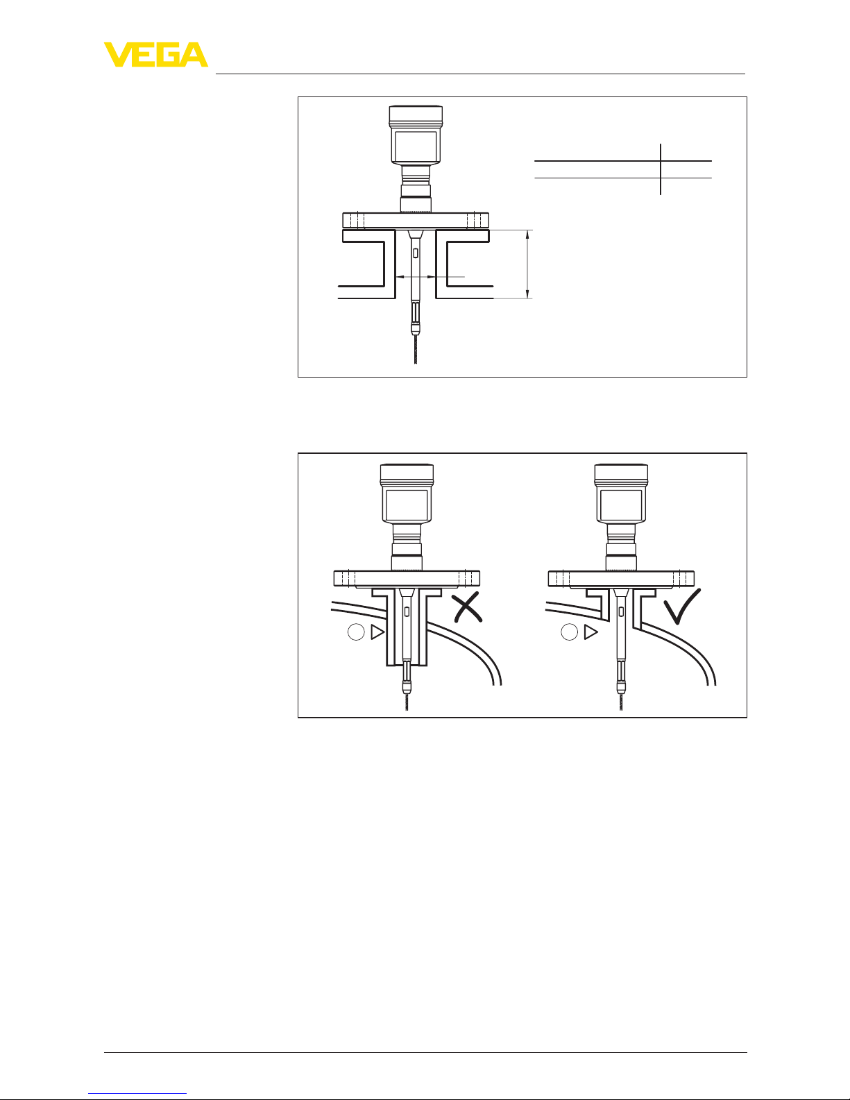
h
d
dh
DN40 ... DN150
> DN150 ... DN200
150
100
_
<
_
<
Fig. 4: Mounting socket
Whenweldingthesocket,makesurethatthesocketisushwiththe
vessel top.
1 2
Fig.5:Socketmustbeinstalledush
1 Unfavourable installation
2 Socketush-optimuminstallation
10
4 Connecting to power supply
VEGAFLEX 81 • Foundation Fieldbus
47589-EN-140324
4 Connecting to power supply
4.1 Connecting
The voltage supply and signal output are connected via the spring-
loaded terminals in the housing.
Connection to the display and adjustment module or to the interface
adapter is carried out via contact pins in the housing.
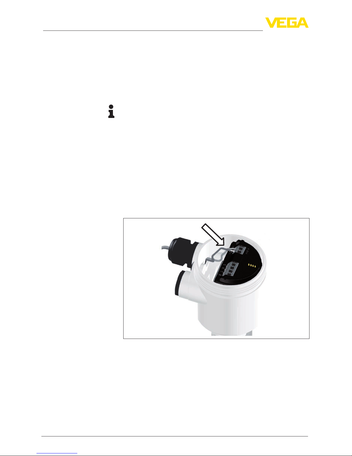
Information:
The terminal block is pluggable and can be removed from the
electronics. To do this, lift the terminal block with a small screwdriver
and pull it out. When reinserting the terminal block, you should hear it
snap in.
Proceed as follows:
1. Unscrew the housing cover
2. If a display and adjustment module is installed, remove it by turn-
ing it slightly to the left.
3. Loosen compression nut of the cable entry gland
4. Removeapprox.10cm(4in)ofthecablemantle,stripapprox.
1 cm (0.4 in) of insulation from the ends of the individual wires
5. Insert the cable into the sensor through the cable entry
Fig.6:Connectionsteps5and6-Singlechamberhousing
Connection technology
Connection procedure
Other manuals for VEGAFLEX 81
18
Table of contents
Other Vega Accessories manuals

Vega
Vega VEGAFLEX 62 User manual

Vega
Vega VEGAFLEX 86 User manual

Vega
Vega VEGABAR 82 User manual

Vega
Vega VEGAPULS WL 61 User manual

Vega
Vega VEGAPULS 69 User manual

Vega
Vega VEGAPULS C 23 User manual

Vega
Vega VEGACAL 60 Series User guide

Vega
Vega VEGABAR 82 User manual

Vega
Vega VEGAFLEX 86 User manual

Vega
Vega VEGAPULS 65 User manual

Vega
Vega POINTRAC 31 User manual

Vega
Vega VEGAPULS 66 User manual

Vega
Vega VEGAPULS 51K User manual

Vega
Vega VEGAPULS C 22 User manual

Vega
Vega VEGAPULS C 21 User manual

Vega
Vega VEGAFLEX 81 User manual

Vega
Vega VEGABAR 39 User manual

Vega
Vega MINITRAC 31 User manual

Vega
Vega VEGAFLEX 86 User manual

Vega
Vega VEGAFLEX 81 User manual


