Vega VEGAFLEX 86 User manual

Quick setup guide
TDR sensor for continuous level and
interface measurement of liquids
VEGAFLEX 86
Foundation Fieldbus
Coax probe
-20 … +250 °C
Document ID: 49740

2
Contents
VEGAFLEX 86 • Foundation Fieldbus
49740-EN-190701
Contents
1 For your safety ......................................................................................................................... 3
1.1 Authorised personnel ....................................................................................................... 3
1.2 Appropriate use................................................................................................................ 3
1.3 Warning about incorrect use............................................................................................. 3
1.4 General safety instructions............................................................................................... 3
1.5 EU conformity................................................................................................................... 4
1.6 NAMUR recommendations .............................................................................................. 4
1.7 Environmental instructions ............................................................................................... 4
2 Product description ................................................................................................................. 5
2.1 Conguration.................................................................................................................... 5
3 Mounting................................................................................................................................... 7
3.1 General instructions for use of the instrument .................................................................. 7
3.2 Mounting instructions ....................................................................................................... 7
4 Connecting to power supply................................................................................................... 8
4.1 Connecting....................................................................................................................... 8
4.2 Wiring plan, single chamber housing................................................................................ 9
4.3 Wiring plan, double chamber housing .............................................................................. 9
5 Set up with the display and adjustment module ................................................................ 11
5.1 Insert display and adjustment module............................................................................ 11
5.2 Parameter adjustment - Quick setup .............................................................................. 12
6 Supplement ............................................................................................................................ 15
6.1 Technical data ................................................................................................................ 15
Information:
This quick setup guide enables quick setup and commissioning of
your instrument.
Youcanndsupplementaryinformationinthecorresponding,more
detailed Operating Instructions Manual as well as the Safety Manual
thatcomeswithinstrumentswithSILqualication.Thesemanualsare
available on our homepage.
Operating instructions VEGAFLEX 86 - Foundation Fieldbus -
Coax probe, -20 … +250 °C: Document-ID 49474
Editing status of the quick setup guide: 2019-06-27

3
1 For your safety
VEGAFLEX 86 • Foundation Fieldbus
49740-EN-190701
1 For your safety
1.1 Authorised personnel
All operations described in this documentation must be carried out
onlybytrained,qualiedpersonnelauthorisedbytheplantoperator.
During work on and with the device, the required personal protective
equipment must always be worn.
1.2 Appropriate use
VEGAFLEX 86 is a sensor for continuous level measurement.
Youcannddetailedinformationabouttheareaofapplicationin
chapter "Product description".
Operational reliability is ensured only if the instrument is properly
usedaccordingtothespecicationsintheoperatinginstructions
manual as well as possible supplementary instructions.
1.3 Warning about incorrect use
Inappropriate or incorrect use of this product can give rise to applica-
tion-specichazards,e.g.vesseloverllthroughincorrectmounting
or adjustment. Damage to property and persons or environmental
contamination can result. Also, the protective characteristics of the
instrument can be impaired.
1.4 General safety instructions
This is a state-of-the-art instrument complying with all prevailing
regulations and directives.The instrument must only be operated in a
technicallyawlessandreliablecondition.Theoperatorisresponsi-
ble for the trouble-free operation of the instrument.When measuring
aggressive or corrosive media that can cause a dangerous situation
if the instrument malfunctions, the operator has to implement suitable
measures to make sure the instrument is functioning properly.
During the entire duration of use, the user is obliged to determine the
compliance of the necessary occupational safety measures with the
current valid rules and regulations and also take note of new regula-
tions.
The safety instructions in this operating instructions manual, the na-
tional installation standards as well as the valid safety regulations and
accident prevention rules must be observed by the user.
For safety and warranty reasons, any invasive work on the device
beyond that described in the operating instructions manual may be
carried out only by personnel authorised by the manufacturer. Arbi-
traryconversionsormodicationsareexplicitlyforbidden.Forsafety
reasons,onlytheaccessoryspeciedbythemanufacturermustbe
used.
To avoid any danger, the safety approval markings and safety tips on
the device must also be observed and their meaning read in this oper-
ating instructions manual.

4
1 For your safety
VEGAFLEX 86 • Foundation Fieldbus
49740-EN-190701
1.5 EU conformity
ThedevicefullsthelegalrequirementsoftheapplicableEUdirec-
tives.ByaxingtheCEmarking,weconrmtheconformityofthe
instrument with these directives.
The EU conformity declaration can be found on our homepage.
Electromagnetic compatibility
Instrumentsinfour-wireorEx-d-iaversionaredesignedforuseinan
industrial environment. Nevertheless, electromagnetic interference
from electrical conductors and radiated emissions must be taken into
account, as is usual with class A instruments according to EN 61326-
1.Iftheinstrumentisusedinadierentenvironment,theelectromag-
netic compatibility to other instruments must be ensured by suitable
measures.
1.6 NAMUR recommendations
NAMUR is the automation technology user association in the process
industry in Germany. The published NAMUR recommendations are
acceptedasthestandardineldinstrumentation.
ThedevicefullstherequirementsofthefollowingNAMURrecom-
mendations:
• NE 21 – Electromagnetic compatibility of equipment
• NE53–Compatibilityofelddevicesanddisplay/adjustment
components
• NE107–Self-monitoringanddiagnosisofelddevices
For further information see www.namur.de.
1.7 Environmental instructions
Protection of the environment is one of our most important duties.
That is why we have introduced an environment management system
with the goal of continuously improving company environmental pro-
tection.Theenvironmentmanagementsystemiscertiedaccording
to DIN EN ISO 14001.
Pleasehelpusfullthisobligationbyobservingtheenvironmental
instructions in this manual:
• Chapter "Packaging, transport and storage"
• Chapter "Disposal"

5
2 Product description
VEGAFLEX 86 • Foundation Fieldbus
49740-EN-190701
2 Product description
2.1 Conguration
Thetypelabelcontainsthemostimportantdataforidenticationand
use of the instrument:
2
1
12
13
14
15
11
10
5
3
6
4
7
8
9
Fig. 1: Layout of the type label (example)
1 Instrument type
2 Product code
3 Approvals
4 Power supply and signal output, electronics
5 Protection rating
6 Probe length (measurement accuracy optional)
7 Process and ambient temperature, process pressure
8 Material wetted parts
9 Order number
10 Serial number of the instrument
11 Symbol of the device protection class
12 ID numbers, instrument documentation
13 Reminder to observe the instrument documentation
14 NotiedauthorityforCEmarking
15 Approval directives
The type label contains the serial number of the instrument. With it
youcanndthefollowinginstrumentdataonourhomepage:
• Product code (HTML)
• Delivery date (HTML)
• Order-specicinstrumentfeatures(HTML)
• Operating instructions and quick setup guide at the time of ship-
ment (PDF)
• Order-specicsensordataforanelectronicsexchange(XML)
• Testcerticate(PDF)-optional
Move to "www.vega.com"andenterinthesearcheldtheserial
number of your instrument.
Alternatively, you can access the data via your smartphone:
• Download the VEGA Tools app from the "Apple App Store" or the
"Google Play Store"
Type label
Serial number - Instru-
ment search

6
2 Product description
VEGAFLEX 86 • Foundation Fieldbus
49740-EN-190701
• ScantheDataMatrixcodeonthetypelabeloftheinstrumentor
• Enter the serial number manually in the app

7
3 Mounting
VEGAFLEX 86 • Foundation Fieldbus
49740-EN-190701
3 Mounting
3.1 General instructions for use of the instrument
Protect your instrument against moisture ingress through the following
measures:
• Use a suitable connection cable (see chapter "Connectingto
power supply")
• Tighten the cable gland or plug connector
• Lead the connection cable downward in front of the cable entry or
plug connector
This applies mainly to outdoor installations, in areas where high
humidityisexpected(e.g.throughcleaningprocesses)andoncooled
or heated vessels.
Note:
Makesurethatthedegreeofcontaminationspeciedinchapter
"Technical data"meetstheexistingambientconditions.
Note:
Make sure that during installation or maintenance no moisture or dirt
can get inside the instrument.
To maintain the housing protection, make sure that the housing lid is
closed during operation and locked, if necessary.
3.2 Mounting instructions
In vessels with conical bottom it can be advantageous to mount the
sensor in the center of the vessel, as measurement is then possible
nearly down to the lowest point of the bottom. Keep in mind that
measurement all the way down to the tip of the probe may not be pos-
sible.Theexactvalueofthemin.distance(lowerdeadzone)isstated
in chapter "Technical data".
Fig. 2: Vessel with conical bottom
Protection against mois-
ture
Installation position

8
4 Connecting to power supply
VEGAFLEX 86 • Foundation Fieldbus
49740-EN-190701
4 Connecting to power supply
4.1 Connecting
The voltage supply and signal output are connected via the spring-
loaded terminals in the housing.
Connection to the display and adjustment module or to the interface
adapter is carried out via contact pins in the housing.
Information:
The terminal block is pluggable and can be removed from the
electronics.To do this, lift the terminal block with a small screwdriver
and pull it out. When reinserting the terminal block, you should hear it
snap in.
Proceed as follows:
1. Unscrew the housing lid
2. If a display and adjustment module is installed, remove it by turn-
ing it slightly to the left
3. Loosen compression nut of the cable gland and remove blind
plug
4. Removeapprox.10cm(4in)ofthecablemantle,stripapprox.
1 cm (0.4 in) of insulation from the ends of the individual wires
5. Insert the cable into the sensor through the cable entry
1 2
Fig.3:Connectionsteps5and6
1 Single chamber housing
2 Double chamber housing
6. Insert the wire ends into the terminals according to the wiring plan
Information:
Solidcoresaswellasexiblecoreswithwireendsleevesareinsert-
eddirectlyintotheterminalopenings.Incaseofexiblecoreswithout
end sleeves, press the terminal from above with a small screwdriver,
the terminal opening is then free.When the screwdriver is released,
the terminal closes again.
Youcanndfurtherinformationonthemax.wirecross-sectionunder
"Technicaldata-Electromechanicaldata".
7. Check the hold of the wires in the terminals by lightly pulling on
them
Connection technology
Connection procedure

9
4 Connecting to power supply
VEGAFLEX 86 • Foundation Fieldbus
49740-EN-190701
8. Connect the screen to the internal ground terminal, connect the
externalgroundterminaltopotentialequalisation
9. Tighten the compression nut of the cable entry gland. The seal
ring must completely encircle the cable
10. Reinsert the display and adjustment module, if one was installed
11. Screw the housing lid back on
Theelectricalconnectionisnished.
4.2 Wiring plan, single chamber housing
Thefollowingillustrationappliestothenon-Ex,Ex-iaandEx-d-ia
version.
12
( ) (-)
1
5
0
1
0
1
+678
Bus
2
3
4
5
Fig.4:Electronicsandconnectioncompartment-singlechamberhousing
1 Voltage supply, signal output
2 Contactpinsforthedisplayandadjustmentmoduleorinterfaceadapter
3 Simulation switch ("1" = mode for simulation release)
4 Forexternaldisplayandadjustmentunit
5 Ground terminal for connection of the cable screening
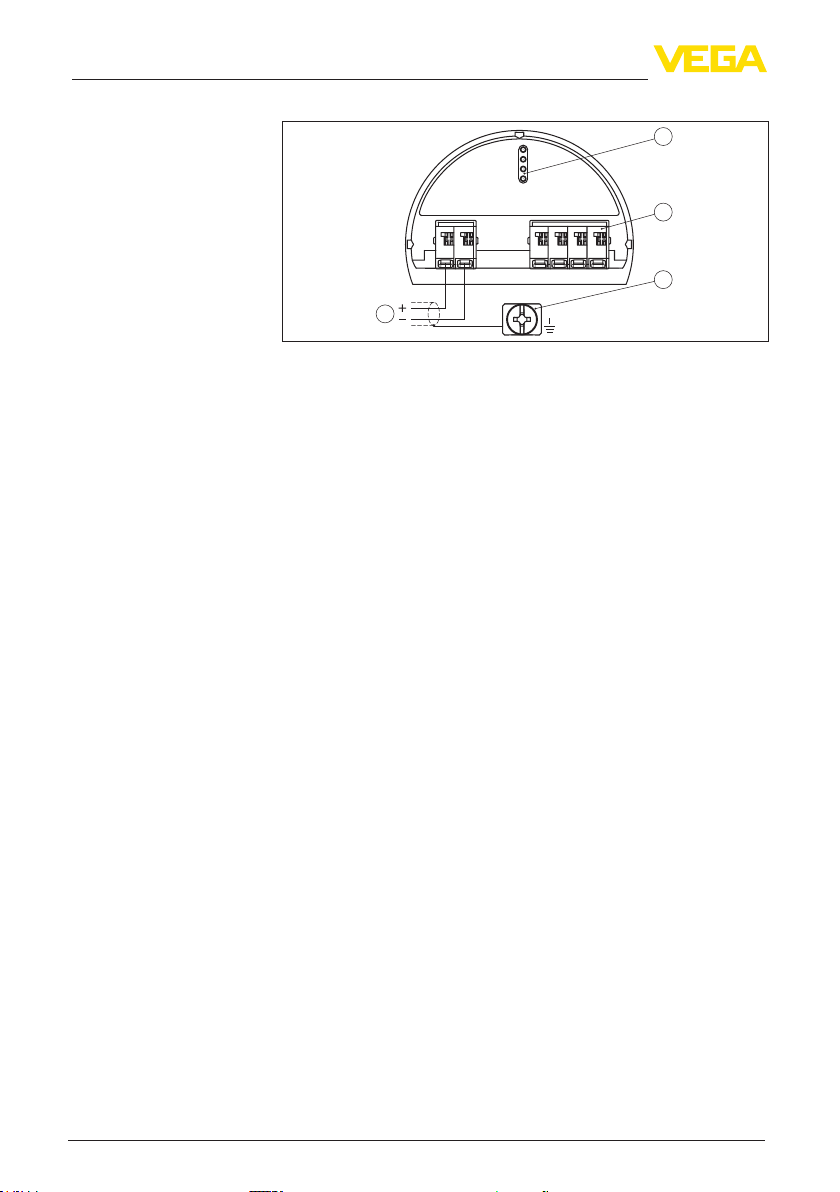
4.3 Wiring plan, double chamber housing
Thefollowingillustrationsapplytothenon-ExaswellastotheEx-ia
version.
Electronics and connec-
tion compartment
10
4 Connecting to power supply
VEGAFLEX 86 • Foundation Fieldbus
49740-EN-190701
Bus
5
12
+
( ) (-)
678
2
3
4
1
Fig.5:Connectioncompartment-doublechamberhousing
1 Voltage supply, signal output
2 Fordisplayandadjustmentmoduleorinterfaceadapter
3 Forexternaldisplayandadjustmentunit
4 Ground terminal for connection of the cable screening
Connection compartment
Other manuals for VEGAFLEX 86
15
Table of contents
Other Vega Accessories manuals

Vega
Vega VEGAPULS Air 23 User manual

Vega
Vega MINITRAC 31 User manual

Vega
Vega VEGASWING 61 User manual

Vega
Vega VEGABAR 28 User manual

Vega
Vega VEGAFLEX 81 User manual

Vega
Vega VEGAFLEX 82 User manual

Vega
Vega VEGAPULS 62 User manual

Vega
Vega VEGAPULS 66 User manual

Vega
Vega VEGAPULS 6X User manual

Vega
Vega POINTRAC 31 User manual

Vega
Vega VEGAFLEX 81 User manual

Vega
Vega VEGABAR 39 User manual

Vega
Vega VEGAPULS 6X User manual

Vega
Vega VEGAPULS 6X User manual

Vega
Vega VEGAFLEX 81 User manual

Vega
Vega VEGACAP 65 User manual

Vega
Vega VEGAPULS 62 User manual

Vega
Vega VEGAFLEX 82 User manual

Vega
Vega VEGAFLEX 65 User manual

Vega
Vega VEGABAR 82 User manual


