ST STEVAL-L6983IV1 User manual

Introduction
The STEVAL-L6983IV1 evaluation board is based on the L6983I, 38 V, 10 W synchronous iso-buck converter designed for
isolated applications.
The primary output voltage can be accurately adjusted, whereas the isolated secondary output is derived by using a given
transformer ratio. No optocoupler is required. The primary sink capability up to -4.5A (even during soft-start) allows transferring
a proper energy to the secondary side as well as enabling a tracked soft-start of the secondary output. The control loop is
based on a peak current mode architecture and the device operates in forced PWM. The 390 ns blanking time filters oscillations,
generated by the transformer leakage inductance, making the solution more robust.
The compact QFN-16 3x3mm package and the internal compensation of the L6983I help minimize the design complexity and
size.
The switching frequency can be programmed in the 200 kHz - 1 MHz range with an optional spread spectrum for improved
EMC.
The EN pin provides the enable/disable functionality. The typical shutdown current is 2 µA when disabled. As soon as the EN
pin is pulled-up, the device is enabled, and the internal 1.3 ms soft start takes place.
The L6983I features the power good open collector that monitors the FB voltage. Pulse by pulse, the current sensing on both
power elements implements an effective constant current protection. The thermal shutdown prevents thermal run-away. Due to
the primary reverse current limit, the secondary output is protected against short-circuit events.
The evaluation board generates an isolated unregulated voltage and provides the possibility to use a post-regulation to generate
a dual voltage (layout available on the bottom of the PCB, components not mounted).
Figure 1. STEVAL-L6983IV1 evaluation board
Getting started with STEVAL-L6983IV1 evaluation board based on L6983I, 38V,
10W synchronous iso-buck converter for isolated applications
UM3110
User manual
UM3110 - Rev 1 - March 2023
For further information contact your local STMicroelectronics sales office. www.st.com

1Getting started
1.1 Safety instructions
This board is intended to be used by skilled technical personnel who are suitably qualified and familiar with the
installation, use, and maintenance of power electronic systems. The same personnel must be aware of and must
apply national accident prevention rules.
The electrical installation has to be completed in accordance with the appropriate requirements (that is, cross-
sectional areas of conductors, fusing, and GND connections).
1.2 Functional block diagram
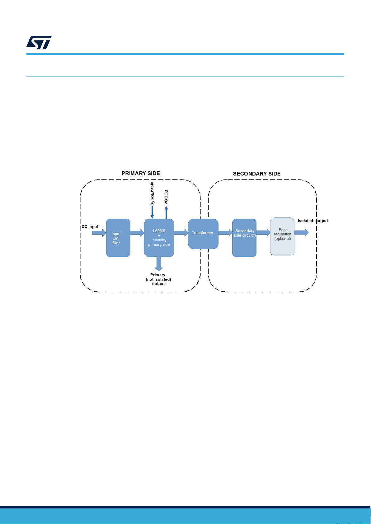
Figure 2. STEVAL-L6983IV1 block diagram
1.3 Features
• Designed for iso-buck topology
• 4 V to 38 V operating input voltage
• Primary output voltage regulation
• No optocoupler required
• 4.5 A source/sink peak primary current capability
• Peak current mode architecture in forced PWM operation
• 300 ns blanking time
• 25 μA operating quiescent current
• 200 kHz to 1 MHz programmable switching frequency. Stable with low ESR capacitor: min 2µF
• Internal compensation network
• 2 μA shutdown current
• Internal soft start
• Enable
• Overvoltage protection
• Thermal protection
• Optional spread spectrum for improved EMC
• Power good
• Synchronization with external clock
• QFN16 3x3 mm package
UM3110
Getting started
UM3110 - Rev 1 page 2/29

2How to use the board
The STEVAL-L6983IV1 is configured to deliver 5 V at the primary non-isolated output and an unregulated voltage
at the isolated output that varies with the applied load (see load regulation curves in section 8). The switching
frequency is set to 400 kHz.
To use the board, follow the procedure below.
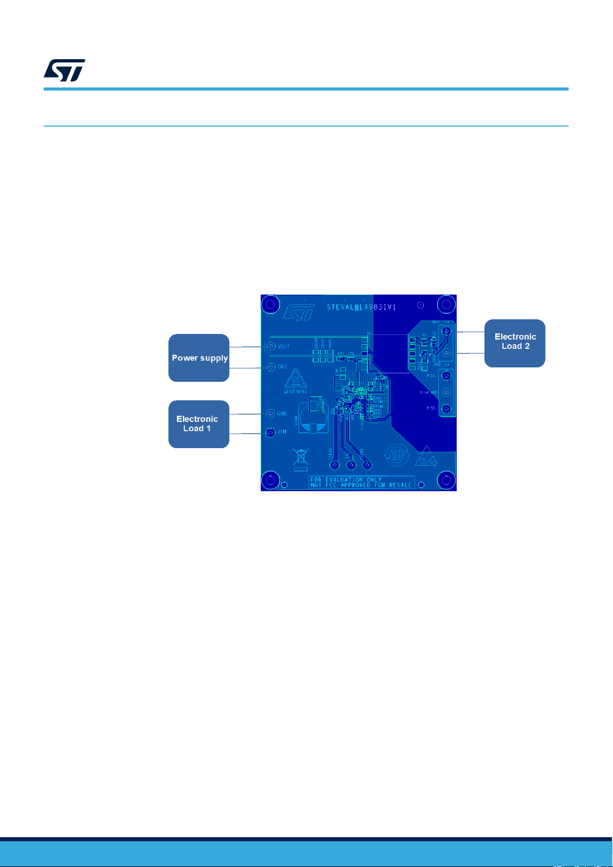
Step 1. Connect the power supply to the test points of VIN and GND.
Step 2. Connect the load to the primary non-isolated output (if any) as well as to the secondary isolated output.
Step 3. Set the supply voltage VIN from 8 V to 38 V and switch the power supply on.
Step 4. Regulate both active loads.
Figure 3. STEVAL-L6983IV1 basic test setup
Note: The STEVAL-L6983IV1 embeds the L6983I. The STEVAL-L6983IV1 is however suitable for the
A6983I too. If the A6983I should be tested, simply replace the L6983I with the A6983I.
UM3110
How to use the board
UM3110 - Rev 1 page 3/29

3Connectors and test points
3.1 VIN – TPxx
This connector is used for the input supply voltage. This voltage is provided, through the input EMI filter, to the
device VIN pin.
A power supply ranging from 4 V to 38 V should be connected to this test point, setting a proper current limit.
The wire connection should be as short as possible to avoid or limit possible oscillations due to the parasitic
inductance of the wire and the input capacitor.
3.2 GND1 and GNDprim – TPxx and TPxxx
GND1 and GNDprim are, respectively, the return path of the input and output capacitors. Wires used for this
connection should be as short as possible.
3.3 VOUT1 – TPxx
This is the connector for the primary non-isolated output voltage. To load the primary output, connect a resistor or
an active load to this test point. Short wires are recommended.
3.4 EN/SYNCH – TPxx
By default, the EN pin is pulled-up to the input voltage through the resistor Ren1. This makes the device always
enabled. The same test-point can be used to apply an external signal for synchronization.
3.5 PGOOD – TPxx
This test point is directly connected to the PGOOD pin.
3.6 VOUTiso – TPxx
This test point provides the isolated output voltage (unregulated). When completely unloaded, the voltage at this
pin could be much higher than the theoretical value (N*VOUT1). Short wire connection from this test point to the
load is recommended.
3.7 GNDiso – TPxx
The voltage at this test point represents the reference for the isolated voltage. Short connection is recommended.
3.8 VISO+, VISO- and VISO_gnd – TPxx
The isolated output voltage can be post-regulated and used to generate a dual voltage. On the bottom side of
the PCB, the layout for post-regulation is available (components to be assembled). If the components of the post
regulation circuitry are assembled, the VISO+, VISO- and VISO_gnd test points provide a positive (VISO+) and
negative voltage (VISO-), both referred to VISO_gnd.
UM3110
Connectors and test points
UM3110 - Rev 1 page 4/29

4Input EMI filter
The STEVAL-L6983IV1 is compliant with CISPR16-4-2 thanks to the embedded EMI filter (bottom side).
The EMI filter consists of:
• A double pi filter with an inductor (Lf2)
• A ferrite bead (Lf1)
• Three MLCC capacitors (Cf1, Cf2, and Cf3)
• An electrolytic bulk capacitor used as bulk energy storage (Cin4)
UM3110
Input EMI filter
UM3110 - Rev 1 page 5/29

5Board setting capability
The STEVAL-L6983IV1 provides the possibility to change some settings according to the application conditions.
Switching frequency
By default, the Rfsw2 is equal to 0 Ω. It sets the switching frequency to 400 kHz and enables the dithering.
By changing the value of Rfsw1, a different switching frequency is set. Using the Rfsw1 instead of Rfsw2 disables
the dithering function (see Table 1. Switching frequency and dithering setting).
Figure 4. Resistors on the PCB used to set the switching frequency and the dithering
Table 1. Switching frequency and dithering setting
Symbol Option RVCC(KΩ) RGND(KΩ) Min. Typ. Max. Unit
FSW
Dithering
1.8 N.C. 200 kHz
0 N.C. 400 kHz
3.3 N.C. 500 kHz
5.6 N.C. 700 kHz
10 N.C. 1000 kHz
No dithering
N.C. 1.8 200 kHz
N.C. 0 360 400 440 kHz
N.C. 3.3 500 kHz
N.C. 5.6 630 700 770 kHz
N.C. 10 900 1000 1100 kHz
Enable thresholds
The STEVAL-L6983IV1 is equipped with the REN1 = 100 kΩ as pull-up resistor to keep the device always
enabled. The power-up threshold can be adjusted by properly selecting the REN1 and REN2, according to the
following equations:
VPowerUP = 1.2 ⋅1 + REN1
REN2
VPowerDown = 1.0 ⋅1 + REN1
REN2
UM3110
Board setting capability
UM3110 - Rev 1 page 6/29

Figure 5. Resistors to enable thresholds setting
Primary output voltage
The primary (non-isolated) output voltage is set to 5 V. If a different voltage is desired, the output resistor divider
should be adjusted according to the following equation:
VOUT_prim = 0.85 ⋅1 + RFB1
RFB2
Figure 6. Resistors of the primary output divider
Note: Changing the value of the primary output voltage implies the variation of the isolated output voltage too.
UM3110
Board setting capability
UM3110 - Rev 1 page 7/29

6Schematic diagrams
Figure 7. STEVAL-L6983IV1 circuit schematic (1 of 2)
Optional (bottom)
10uF 10uF 10uF 100uF 10uF 1uF 1uF
6.8uH
Ferrite 220ohm
75k
360k
0R NM
1uF
0R
100nF
NM NM
NM
OR
NM
NM
NM
1uF
100R 100K
NM
NM
22uF 22uF 22uF NM
300R 180pF
STPS1170AF
10uF
Rfb2
Rbs
Rs1
VIN
Rfsw1
Rs2
Cin1
Cvcc
Cf1
PGOOD
GNDpri
+
Cin4
Cf3 Cin3
Cf2
Cout2
U1
L6983NQTR
VIN1 1
VINLDO 2
SGND1 3
EN/CLKIN 4
PGOOD 5
6
VBIAS
FB 7
FSW 8
VCC
9
SGND2
10
BOOT
11
VIN2
12
EP1-SGND
17
13 PGND1
SW1
14
SW2
15
16 PGND2
Rf2
GND1
Lf2
En
Rpg2
Cs2
Lf1
Rfsw2
Cin2
Cb
VOUT_iso
GND_iso
Rfb1
Cldo
Rpg1
D1
2 1
Csec
Cbs
VOUT1
Ren1
Rb
U2
ZB1346-AE
.
1
.
2
.
3
.
4
.
5.6
.7
.8
.10
.9
Cout4
Clkin
Ren2
Cck
Cout1
Rf1
Rldo
Cff
Cs1
Cout3
Figure 8. STEVAL-L6983IV1 circuit schematic (2 of 2) - post regulation (not mounted, bottom side)
Vout_iso
GND_iso
NM
NM
NM
NM
NM
NM
NM
NM
NM
NM
Dz1
Ciso+
R3
U3 LDO40LPU33RY
GND
1
EN
2
VIN
3
VOUT 4
VSENSE 5
ADJ 6
EPAD 7
VISO_gnd
C1
Ciso-
R1
Dz2
Q1
VISO+
VISO-
R2
UM3110
Schematic diagrams
UM3110 - Rev 1 page 8/29

7Bill of materials
Table 2. BOM
Item Q.ty Ref. Part/value Description Manufacturer Order code
1 1 U1
L6983IQTR,
QFPN
3X3X0.80 16L
PITCH 0.50
38 V 10 W
synchronous
iso-buck
converter for
isolated
applications
ST L6983IQTR
2 1 U2 SMD 10 pins
EPQ13 Transformer Coilcraft ZB1346-AE
3 1 U3 LDO40LPURY,
DFN6 3x3
400 mA, 38 V
low-dropout
regulator, with
45 µA quiescent
current (not
mounted)
ST LDO40LPURY
4 1 Q1 2STR1215,
SOT-23
Low voltage
fast-switching
NPN power
transistor (not
mounted)
ST 2STR1215
5 1 R1 0603 0.25 SMD resistor
(not mounted) - -
6 1 R2 0603 0.25 SMD resistor
(not mounted) - -
7 1 R3 0603 0.25 SMD resistor
(not mounted) - -
8 1 Rs1 0805 0.25 SMD resistor
(not mounted) - -
9 1 Rb 0Ω 0603 0.25
1% SMD resistor YAGEO RC0603FR-070RL
10 1 Rs2 300Ω 0805 0.25
1% SMD resistor Vishay CRCW0805300RFKEAHP
11 1 Rf1 0603 0.25 SMD resistor
(not mounted) - -
12 1 Rf2 0603 0.25 SMD resistor
(not mounted) - -
13 1 Ren1 100kΩ 0603
0.25 1% SMD resistor YAGEO AC0603FR-07100KL
14 1 Ren2 0603 0.25 SMD resistor
(not mounted) - -
16 1 Rfb1 360kΩ 0603
0.25 1% SMD resistor YAGEO RC0603FR-0775KL
15 1 Rfb2 75kΩ 0603 0.25
1% SMD resistor YAGEO RC0603FR-07360KL
17 1 Rfsw1 0Ω 0603 0.25
1% SMD resistor YAGEO RC0603FR-070RL
18 1 Rfsw2 0603 0.25 SMD resistor
(not mounted) - -
19 1 Rpg2 0603 0.25 SMD resistor
(not mounted) - -
UM3110
Bill of materials
UM3110 - Rev 1 page 9/29

Item Q.ty Ref. Part/value Description Manufacturer Order code
20 1 Rpg1 0603 0.25 SMD resistor
(not mounted) - -
21 1 Rbs 0Ω 0603 0.25
1% SMD resistor YAGEO RC0603FR-070RL
22 1 Rldo 100Ω 0603 0.25
1% SMD resistor YAGEO RC0603FR-10100RL
23 1 C1 0603 MLCC (not
mounted) - -
24 1 Cldo 1uF 0603 50
10% MLCC
Samsung
Electro
Mechanics
CL10A105KB8NNNC
25 1 Cff 0603 MLCC (not
mounted)
26 1 Cb 100nF 0603 50
10% MLCC TDK CGA3E2X7R1H104K080AA
27 1 Cs1 0603 MLCC (not
mounted) - -
28 1 Cin1 10uF 1206 50
10% MLCC
Samsung
Electro
Mechanics
CL31B106KBHNNNE
29 2 Cin2, Cin3 1uF 0805 50
20% MLCC TDK CGA4J3X7R1H105M125AB
30 1 Cin4
100uF
10x10mm 50
20%
Aluminium
Organic
Polymer
Capacitor
KEMET A768MS107M1HLAV024
31 3 Cout1, Cout2,
Cout3
22uF 1206 16
20% MLCC Taiyo Yuden EMK316BB7226ML-T
32 1 Ciso+ 0805 MLCC (not
mounted) - -
33 1 Ciso- 0805 MLCC (not
mounted) - -
34 1 Cs2 180pF 0603 50
1% MLCC Vishay VJ0603A181FXAPW1BC
35 4 Csec, Cf1, Cf2,
Cf3
10uF 1206 50
10% MLCC
Samsung
Electro
Mechanics
CL31B106KBHNNNE
39 1 Cck 0603 MLCC (not
mounted) - -
40 1 Cvcc 1uF 0603 16
10% MLCC TDK CGA3E1X7R1C105K080AC
41 1 Cbs 0603 MLCC (not
mounted) - -
42 1 Cout4 0603 MLCC (not
mounted) - -
43 1 Lf1 220Ω 0805 3
25% Ferrite bead TDK MPZ2012S221ATD25
44 1 Lf2 6.8uH 4x4mm
3.9 20% Inductor Coilcraft XGL4030-682MEC
45 1 D1 STPS1170AF,
SMA Flat
170 V, 1 A
power Schottky
rectifier
ST STPS1170AF
UM3110
Bill of materials
UM3110 - Rev 1 page 10/29
Table of contents
Other ST Motherboard manuals

ST
ST STM32H753I-EVAL User manual

ST
ST STMPE821 User manual

ST
ST STEVAL-IHM022V1 User manual

ST
ST STM3210B-EVAL User manual

ST
ST STM32373C-EVAL User manual

ST
ST STM32 Nucleo User manual

ST
ST SPC572LADPT80S User manual

ST
ST VIPower VIPer22A-E Installation and operating instructions

ST
ST STM32L4P5G-DK User manual

ST
ST M24LR64-R User manual

ST
ST STM3220F-EVAL User manual

ST
ST SPC564A-DISP Installation and operating instructions

ST
ST STSW-STUSB002 User manual

ST
ST EVALST-ISOSD61L User manual

ST
ST UM2313 User manual

ST
ST EVAL-L99DZ200 User manual

ST
ST STEVAL-IPMnM1S User manual

ST
ST L9679E-EVB User manual

ST
ST NUCLEO-H745ZI-Q User manual

ST
ST STM320518-EVAL User manual