Sony HCD-RV20 User manual

1
Ver 1.1 2003. 08
Model Name Using Similar Mechanism NEW
CD CD Mechanism Type CDM74-30BD62
Section Base Unit Name BU-30BD62
Optical Pick-up Name A-MAX.3
Tape Deck Model Name Using Similar Machanism NEW
Section Tape Transport Mechanism Type RV20: CWM43FF-13
RV50/RV60: CWM43RR-23
SERVICE MANUAL
E Model
HCD-RV20/RV50/RV60
Amplifier section
HCD-RV20:
The following measured at AC 120, 127, 220, 240 V,
50/60 Hz
DIN power output (rated):
80 + 80 watts
(6 ohms at 1 kHz, DIN)
Continuous RMS power output (reference):
100 + 100 watts (6 ohms at
1 kHz, 10% THD)
HCD-RV60:
Front speaker
The following measured at AC 120, 127, 220, 240 V,
50/60 Hz
DIN power output (rated):
160 + 160 watts
(6 ohms at 1 kHz, DIN)
Continuous RMS power output (reference):
200 + 200 watts (6 ohms at
1 kHz, 10% THD)
Music power output (reference):
400 + 400 watts (6 ohms at
1 kHz, 10% THD)
HCD-RV50:
The following measured at AC 120, 127, 220, 240 V,
50/60 Hz
DIN power output (rated):
115 + 115 watts
(6 ohms at 1 kHz, DIN)
Continuous RMS power output (reference):
140 + 140 watts (6 ohms at
1 kHz, 10% THD)
SPECIFICATIONS
Inputs
HCD-RV20:
GAME INPUT AUDIO L/R (phono jacks):
voltage 250 mV,
impedance 47 kilohms
GAME INPUT VIDEO (phono jack):
1 Vp-p, 75 ohms
MIC (phone jack): sensitivity 1 mV,
impedance 10 kilohms
Outputs
PHONES (stereo mini jack):
accepts headphones of
8 ohms or more
VIDEO OUT (phono jack):
max. output level
1 Vp-p, unbalanced, Sync
negative, load impedance
75 ohms
SPEAKER: accepts impedance of 6 to
16 ohms
Sony Corporation
Home Audio Company
Published by Sony Engineering Corporation
9-877-378-02
2003H04-1
© 2003. 08
– Continued on next page –
COMPACT DISC DECK RECEIVER
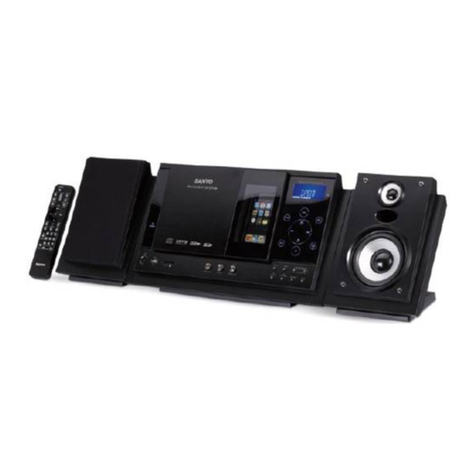
•HCD-RV20/RV50/RV60 is the
tuner, deck, CD and amplifier
sectioninMHC-RV20/RV50/RV60. (Photo: HCD-RV50)

2
HCD-RV20/RV50/RV60
SAFETY-RELATED COMPONENT WARNING!!
COMPONENTS IDENTIFIED BY MARK 0OR DOTTED LINE
WITH MARK 0ON THE SCHEMATIC DIAGRAMS AND IN
THE PARTS LIST ARE CRITICAL TO SAFE OPERATION.
REPLACE THESE COMPONENTS WITH SONY PARTS WHOSE
PART NUMBERS APPEAR AS SHOWN IN THIS MANUAL OR
IN SUPPLEMENTS PUBLISHED BY SONY.
HCD-RV50/RV60:
MD (VIDEO) IN L/R (phono jacks):
voltage 450/250 mV,
impedance 47 kilohms
GAME INPUT AUDIO L/R (phono jacks):
voltage 250 mV,
impedance 47 kilohms
GAME INPUT VIDEO (phono jack):
1 Vp-p, 75 ohms
MIC (phone jack): sensitivity 1 mV,
impedance 10 kilohms
Outputs
PHONES (stereo mini jack):
accepts headphones of
8 ohms or more
VIDEO OUT (phono jack):
max. output level 1 Vp-p,
unbalanced, Sync
negative, load impedance 75 ohms
MD (VIDEO) OUT L/R (phono jacks):
impedance 1 kilohms
SPEAKER: accepts impedance of 6 to
16 ohms
SURROUND SPEAKER (HCD-RV60 only)
accepts impedance of 24
ohms
CD player section
System Compact disc and digital
audio system
Laser Semiconductor laser
(λ=780 nm)
Emission duration:
continuous
Frequency response 2 Hz – 20 kHz (±0.5 dB)
Wavelength 780 – 790 nm
Signal-to-noise ratio More than 90 dB
Dynamic range More than 90 dB
Video color system format
NTSC, PAL
Tape deck section
Recording system 4-track 2-channel stereo
Frequency response 50 – 13,000 Hz (±3 dB),
using Sony TYPE I
cassettes
Wow and flutter ±0.15% W.Peak (IEC)
0.1% W.RMS (NAB)
±0.2% W.Peak (DIN)
Tuner section
FM stereo, FM/AM superheterodyne tuner
FM tuner section
Tuning range 87.5 – 108.0 MHz
Antenna FM lead antenna
Antenna terminals 75 ohms unbalanced
Intermediate frequency 10.7 MHz
AM tuner section
Tuning range
Middle Eastern model: 531 – 1,602 kHz (with the tuning
interval set at 9 kHz)
Other models: 530 – 1,710 kHz (with the tuning
interval set at 10 kHz)
531 – 1,602 kHz (with the tuning
interval set at 9 kHz)
Antenna AM loop antenna
Antenna terminals External antenna terminal
Intermediate frequency 450 kHz
Speaker
HCD-RV20:
Speaker system 3-way, 3-unit,
bass-reflex type
Speaker units
Woofer: 13 cm, cone type
Sub woofer: 13 cm, cone type
Tweeter: 5 cm, cone type
Nominal impedance 6 ohms
Dimensions (w/h/d) Approx. 240 ×325 ×243 mm
Mass Approx. 4.3 kg net per
speaker
Front speaker SS-RV990 for HCD-RV60/RV50:
Speaker system 3-way, 3-unit, bass-reflex
type
Speaker units
Sub Woofer: 15 cm, cone type
Woofer: 15 cm, cone type
Tweeter: 5 cm, cone type
Nominal impedance 6 ohms
Dimensions (w/h/d) Approx. 240 ×363 ×290 mm
Mass Approx. 4.7 kg net per
speaker
Surround speaker SS-RSV60 for HCD-RV60:
Speaker system 3-way, 3-unit, bass-reflex
type
Speaker units
Woofer: 13 cm, cone type
Tweeter: 5 cm, cone type
Super tweeter: 2 cm, dome type
Nominal impedance 24 ohms
Dimensions (w/h/d) Approx. 195 ×325 ×225 mm
Mass Approx. 2.3 kg net per
speaker
General
Power requirements
Saudi Arabian model: 120 – 127 V/220 V or
230 – 240 V AC,
50/60 Hz
Adjustable with voltage
selector
Thai model: 220 V AC, 50/60 Hz
Other models: 120 V, 220V or 230 –
240 V AC, 50/60 Hz
Adjustable with voltage
selector
Power consumption
HCD-RV20: 110 watts
HCD-RV50: 135 watts
HCD-RV60: 190 watts
Dimensions (w/h/d)
HCD-RV20: Approx. 280 ×325 ×407 mm
HCD-RV50/RV60: Approx. 280 ×325 ×407 mm
Mass
HCD-RV20: Approx. 8.5 kg
HCD-RV50: Approx. 9.0 kg
HCD-RV60: Approx. 11.5 kg
Supplied accessories: AM loop antenna (1)
Remote Commander (1)
Batteries (2)
FM lead antenna (1)
Speaker pads
HCD-RV20 (8)
HCD-RV50 (8)
HCD-RV60 (16)
Video cable (1)
Design and specifications are subject to change without
notice.

3
CAUTION
Use of controls or adjustments or performance of procedures
other than those specified herein may result in hazardous
radiation exposure.
HCD-RV20/RV50/RV60
NOTES ON HANDLING THE OPTICAL PICK-UP BLOCK
OR BASE UNIT
The laser diode in the optical pick-up block may suffer electrostatic
breakdown because of the potential difference generated by the
charged electrostatic load, etc. on clothing and the human body.
During repair, pay attention to electrostatic break-down and also
use the procedure in the printed matter which is included in the
repair parts.
The flexible board is easily damaged and should be handled with
care.
NOTES ON LASER DIODE EMISSION CHECK
The laser beam on this model is concentrated so as to be focused on
the disc reflective surface by the objective lens in the optical pick-
up block. Therefore, when checking the laser diode emission,
observe from more than 30 cm away from the objective lens.
Laser component in this product is capable
of emitting radiation exceeding the limit for
Class 1.
Notes on Chip Component Replacement
•Never reuse a disconnected chip component.
•Notice that the minus side of a tantalum capacitor may be
damaged by heat.
Flexible Circuit Board Repairing
•Keep the temperature of soldering iron around 270°C during
repairing.
•Do not touch the soldering iron on the same conductor of the
circuit board (within 3 times).
•Be careful not to apply force on the conductor when soldering
or unsoldering.
MODEL IDENTIFICATION
– BACK PANEL –
MODEL PARTS No.
RV20: E3, E15, SP, MY, PL 4-264-151-0s
RV20: EA 4-264-151-1s
RV50: E3, E15, SP, MY, PL 4-264-151-2s
RV50: EA 4-264-151-3s
RV60: EA 4-264-151-4s
RV60: E3, E15, SP, MY, PL 4-264-151-5s
RV20: TH 4-264-151-6s
RV50: TH 4-264-151-7s
RV60: TH 4-264-151-8s
•Abbreviation
E3 : 240 VAC area in E model
EA : Saudi Arabia model
MY : Malaysia model
SP : Singapore model
TH : Thai model
SETTING AND RELEASING THE CD DISC TRAY LOCK
FUNCTION
This set has a disc tray lock function to prevent discs for
demonstration at shops from theft. While this lock function is set,
the tray will not be delivered out even when the OPEN/CLOSE
button is pressed.
Setting method:
Press the OPEN/CLOSE button while pressing the STOP button.
After a few seconds, the message “LOCKED” will appear on the
fluorescent indicator tube with the tray locked.
Releasing method:
Just as the lock is set, press the OPEN/CLOSE button while
pressing the STOP button.
After a few seconds, the message “UNLOCKED” will appear with
the lock released.
PARTS No.

4
TABLE OF CONTENTS
HCD-RV20/RV50/RV60
1. GENERAL
HCD-RV20 Main Unit ............................................................ 5
HCD-RV20 Remote Control ................................................... 5
HCD-RV50/RV60 Main Unit .................................................. 6
HCD-RV50/RV60 Remote Control .........................................6
2. DISASSEMBLY
2-1. Case (Top) ........................................................................... 8
2-2. CD Door .............................................................................. 8
2-3. CD Mechanism Block .........................................................9
2-4. Front Panel Section ........................................................... 10
2-5. Tape Mechanism Deck ...................................................... 11
2-6. Panel Board, 1 Stream Led Board,
6 Stream Led Board, Remote Board ................................. 11
2-7. Jack Board ......................................................................... 12
2-8. Back Panel Section............................................................ 12
2-9. Main Board ....................................................................... 13
2-10. PowerAmp Board ............................................................. 13
2-11. Video Board, SW Board, Driver Board ............................. 14
2-12. CD Block Assy .................................................................. 14
2-13. Sensor Board ..................................................................... 15
2-14. Motor (TB) Board ............................................................. 15
2-15. Motor (LD) Board .............................................................16
2-16. BD Board .......................................................................... 16
3. DIAGRAMS
3-1. IC Pin Description............................................................. 17
3-2. Circuit Boards Location .................................................... 19
3-3. Printed Wiring Board –CD Mechanism Section (1/2)– .... 20
3-4. Schematic Diagram –CD Mechanism Section (1/2)– ....... 21
3-5. Printed Wiring Boards –CD Mechanism Section (2/2)– ... 22
3-6. Schematic Diagram –CD Mechanism Section (2/2)– ....... 23
3-7. Printed Wiring Board –Video Section– ............................. 24
3-8. Schematic Diagram –Video Section (1/2)– ....................... 26
3-9. Schematic Diagram –Video Section (2/2)– ....................... 27
3-10. Printed Wiring Board –Main Section– .............................. 28
3-11. Schematic Diagram –Main Section (1/3)– ........................ 29
3-12. Schematic Diagram –Main Section (2/3)– ........................ 30
3-13. Schematic Diagram –Main Section (3/3)– ........................ 31
3-14. Printed Wiring Boards –Panel Section– ............................ 32
3-15. Schematic Diagram –Panel Section– ................................ 33
3-16. Printed Wiring Boards –Jack Section–.............................. 34
3-17. Schematic Diagram –Jack Section– ..................................35
3-18. Printed Wiring Board –PowerAmp Section– ................... 36
3-19. Schematic Diagram –PowerAmp Section (1/2)– ............. 37
3-20. Schematic Diagram –PowerAmp Section (2/2)– ............. 38
3-21. Printed Wiring Board
–Transformer Section (HCD-RV20)– ............................... 39
3-22. Printed Wiring Board
–Transformer Section (HCD-RV50)– ............................... 40
3-23. Printed Wiring Board
–Transformer Section (HCD-RV60)– ............................... 41
3-24. Schematic Diagram –Transformer Section– ..................... 42
3-25. IC Block Diagrams............................................................ 43
4. EXPLODED VIEWS
4-1. Main Section ..................................................................... 46
4-2. Front Panel Section (1)...................................................... 47
4-3. Front Panel Section (2)...................................................... 48
4-4. Front Panel Section (3)...................................................... 49
4-5. Main Board Section .......................................................... 50
4-6. CD Mechanism Deck Section (1) ..................................... 51
4-7. CD Mechanism Deck Section (2) ..................................... 52
4-8. Optical Pick-up Section..................................................... 53
5. ELECTRICAL PARTS LIST ........................................ 54

5
HCD-RV20/RV50/RV60
SECTION 1
GENERAL This section is extracted
from instruction manual.
• HCD-RV20
Main Unit

6
HCD-RV20/RV50/RV60
• HCD-RV50/RV60
Main Unit

7
HCD-RV20/RV50/RV60
SECTION 2
DISASSEMBLY
Note : Disassemble the unit in the order as shown below.
2-1. CASE (TOP)
(Page 8)
2-2. CD DOOR
(Page 8)
SET
2-3. CD MECHANISM BLOCK
(Page 9)
2-8. BACK PANEL SECTION
(Page 12)
2-9. MAIN BOARD
(Page 13)
2-12. CD BLOCK ASSY
(Page 14)
2-16. OPTICAL PICK-UP,
BD BOARD
(Page 16)
2-10. POWER AMP BOARD
(Page 13)
2-4. FRONT PANEL SECTION
(Page 10)
2-5. TAPE MECHANISM DECK
(Page 11)
2-6. PANEL BOARD,
1 STREAM LED BOARD,
6 STREAM LED BOARD,
REMOTE BOARD
(Page 11)
2-13. SENSOR BOARD
(Page 15)
2-14. MOTOR (TB) BOARD
(Page 15)
2-15. MOTOR (LD) BOARD
(Page 16)
2-11. VIDEO BOARD,
SW BOARD,
DRIVER BOARD
(Page 14)
2-7. JACK BOARD
(Page 12)

8
HCD-RV20/RV50/RV60
2-2. CD DOOR
Note : Follow the disassembly procedure in the numerical order given.
2-1. CASE (TOP)
case (side-R)
case (side-L)
5
qd
qs
qs
q;
6
two screws (case 3 TP2)
qf
case (top)
8
screw
(+BVTP 3
×
10)
3
screw
(+BVTP 3
×
10
)
9
screw
(+BVTP 3
×
10)
4
screw
(+BVTP 3
×
10)
1
two screws
(case 3 TP2)
qa
two screws (+BVTP 3
×
10)
7
screw (case 3 TP2)
2
screw (case 3 TP2)
2
Pull-out the disc tray.
4
CD door
1
Turn the pulley to the direction of arrow.
pulley
Front panel side
CD mechanism deck (CDM74-30BD62)
3

9
HCD-RV20/RV50/RV60
2-3. CD MECHANISM BLOCK
2
CN701
1
CN301
8
CN312
(flat type)
6
7
3
three
screws
(+BVTP 3
×
10)
9
CD mechanism block
5
screw
(+BVTP 3
×
10
)
4
screw
(+BVTP 3
×
10)
MAIN board
MAIN board

10
HCD-RV20/RV50/RV60
2-4. FRONT PANEL SECTION
1
CN003
2
CN304
(flat type)
5
connector
6
connector
4
CN308
3
CN311
(flat type)
TRANS board
9
three screws (+BVTP 3
×
8
)
0
front panel section
8
screw
(+BVTP 3
×
8
)
7
screw
(+BVTP 3
×
8)
This manual suits for next models
2
Table of contents
Other Sony Stereo System manuals


Sony
Sony MHC-V7D User manual

Sony
Sony LBT-XGR60 User manual

Sony
Sony LBT-XGR600 - Compact Hi-fi Stereo System User manual

Sony
Sony MHC-ECL99BT User manual

Sony
Sony LBT-ZX6 User manual

Sony
Sony CMT-SE1 User manual

Sony
Sony CMT-SP55TC User manual

Sony
Sony HCD-VX550 User manual

Sony
Sony MHC-EC59 User manual

Sony
Sony H.ear go SRS-HG1 User manual