Sony HCD-GRX50 User manual

MICROFILM
SERVICE MANUAL
MINI Hi-Fi COMPONENT SYSTEM
HCD-GRX50/R770/RXD7
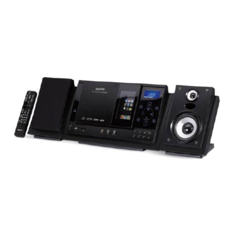
Photo: HCD-GRX50
Dolby noise reduction manufactured under license
from Dolby Laboratories Licensing Corporation.
“DOLBY” and the double-D symbol aare trade-
marks of Dolby Laboratories Licensing Corporation.
Canadian Model
HCD-RXD7
AEP Model
HCD-R770/RXD7
UK Model
HCD-R770
E Model
Australian Model
HCD-GRX50
HCD-GRX50/R770/RXD7 are the Ampli-
fier, CD player, Tape Deck and Tuner
section in HMC-GRX50/R770/RXD7.
SPECIFICATIONS
Amplifier section
Canadian model:
Continuous RMS power output (reference)
70 + 70 watts
(6 ohms at 1 kHz, 10% THD)
Total harmonic distortion less than 0.07%
(6 ohms at 1 kHz, 45 W)
European and Russian models:
DIN power output (rated) 80 + 80 watts
(8 ohms at 1 kHz, DIN)
Continuous RMS power output (reference)
100 + 100 watts
(8 ohms at 1 kHz, 10% THD)
Music power output (reference) 170 + 170 watts
(6 ohms at 1 kHz, 10% THD)
Other models:
The following measured atAC 120, 220, 240 V 50/60 Hz
DIN power output (rated) 110 + 110 watts
(8 ohms at 1 kHz, DIN)
Continuous RMS power output (reference)
140 + 140 watts
(8 ohms at 1 kHz, 10% THD)
– Continued on next page –
Model Name Using Similar Mechanism NEW
CD Mechanism Type CDM38LH-5BD32L
Base Unit Name BU-5BD32L
Optical Pick-up Name KSS-213D/Q-NP
Model Name Using Similar Mechanism NEW
Tape Transport Mechanism Type TCM-230AWR2
CD
Section
Tape deck
Section

– 2 –
Specifications (continued)
Inputs
MD/VIDEO (AUDIO) IN: voltage 450 mV/250mV,
(phono jacks) impedance 47 kilohms
MIX MIC: (phone jack) sensitivity 1 mV, impedance 10
kilohms
Outputs
MD OUT: voltage 250 mV,
(phono jacks) impedance 1 kilohms
PHONES: accepts headphones of 8 ohms
(stereo phone jack) or more
SPEAKER:
Canadian model: accepts impedance of 6 to 16 ohms
Other models: accepts impedance of 8 to 16 ohms
SUPER WOOFER (GRX50/RXD7: Canadian models):
Voltage 1 V, impedance 1 kilohm
CD player section
System Compact disc and digital audio system
Laser Semiconductor laser (λ=780nm)
Emission duration: continuous
Laser output Max. 44.6 µW*
*This output is the value measured at
distance of 200 mm from the objective
lens surface on the Optical Pick-up
Block with 7 mm aperture.
Frequency response 2 Hz - 20 kHz (±0.5 dB)
Wavelength 780 -790 nm
Signal-to-noise ratio More than 90 dB
Dynamic range More than 90 dB
CD OPTICAL DIGITAL OUT
(Square optical connector jack, rear panel)
Wavelength 600 nm
Output Level -18 dBm
Tape player section
Recording system 4-track 2-channel stereo
Frequency response 40 - 13,000 Hz (±3 dB),
(DOLBY NR OFF) using Sony TYPE I cassette
40 - 14,000 Hz (±3 dB),
using Sony TYPE II cassette
Tuner section
FM stereo, FM/AM superheterodyne tuner
FM tuner section
Tuning range 87.5 - 108.0 MHz
Antenna FM lead antenna
Antenna terminals 75 ohm unbalanced
Intermediate frequency 10.7 MHz
UKV tuner section (3 band (FM-AM-UKV) models only)
Tuning range 65.0 - 74.0 MHz
Stereo Plus
AM tuner section
Tuning range
2 Band type:
Canadian model: 530 - 1,710 kHz
(with the interval set at 10 kHz)
531 - 1,710 kHz
(with the interval set at 9 kHz)
European and Russian models: 531 - 1,602 kHz
(with the interval set at 9 kHz)
Other models: 531 - 1,602 kHz
(with the interval set at 9 kHz)
530 - 1,710 kHz
(with the interval set at 10 kHz)
3 Band type:
Middle Eastern models:
MW: 531 - 1,602 kHz
(with the interval set at 9 kHz)
SW: 5.95 - 17.90 MHz
(with the interval set at 5 kHz)
Other models:
MW: 531 - 1,602 kHz
(with the interval set at 9 kHz)
530 - 1,710 kHz
(with the interval set at 10 kHz)
SW: 5.95 - 17.90 MHz
(with the interval set at 5 kHz)
Antenna AM loop antenna
Antenna terminals External antenna terminal
Intermediate frequency 450 kHz
General
Power requirements
Canadian model: 120 V AC, 60 Hz
European and Russian models: 230 V AC, 50/60 Hz
Mexican model: 120 V AC, 50/60 Hz
Australian model: 230 - 240 V AC, 50/60 Hz
Israel and Thai models: 220 V AC, 50/60 Hz
Other models: 120 V, 220 V, or 230 - 240 V AC,
50/60 Hz
Adjustable with voltage selector
Power consumption
Canadian model: 130 watts
European and Russian models: 165 watts
Other models: 160 watts
Dimensions (w/h/d) Approx. 280 ×340 ×395 mm
(111/8 ×131/2× 155/8in.)
Mass
Canadian model: Approx. 9.2 kg
European and Russian models: Approx. 10.1 kg
Other models: Approx. 10 kg
Supplied accessories: AM loop antenna (1)
Remote Commander (1)
Batteries (2)
FM lead antenna (1)
Speaker cords (2)
Front speaker pads (8)
Design and specifications are subject to change without notice.
ATTENTION AU COMPOSANT AYANT RAPPORT
À LA SÉCURITÉ!
LES COMPOSANTS IDENTIFIÉS PAR UNE MARQUE !
SUR LES DIAGRAMMES SCHÉMATIQUES ET LA LISTE
DES PIÈCES SONT CRITIQUES POUR LA SÉCURITÉ
DE FONCTIONNEMENT. NE REMPLACER CES COM-
POSANTS QUE PAR DES PIÈCES SONY DONT LES
NUMÉROS SONT DONNÉS DANS CE MANUEL OU
DANS LES SUPPLÉMENTS PUBLIÉS PAR SONY.
SAFETY-RELATED COMPONENT WARNING!!
COMPONENTS IDENTIFIED BY MARK !OR DOTTED
LINE WITH MARK !ON THE SCHEMATIC DIAGRAMS
AND IN THE PARTS LIST ARE CRITICAL TO SAFE
OPERATION. REPLACE THESE COMPONENTS WITH
SONY PARTS WHOSE PART NUMBERS APPEAR AS
SHOWN IN THIS MANUAL OR IN SUPPLEMENTS PUB-
LISHED BY SONY.

– 3 –
1. SERVICING NOTES ............................................... 3
2. GENERAL
Location of Controls ....................................................... 6
Setting the Time .............................................................. 7
3. DISASSEMBLY ......................................................... 8
4. TEST MODE.............................................................. 11
5. MECHANICAL ADJUSTMENTS....................... 14
6. ELECTRICAL ADJUSTMENTS
DECK Section ................................................................. 14
CD Section ...................................................................... 17
7. DIAGRAMS
7-1. Block Diagram – CD SERVO Section – ........................ 19
7-2. Block Diagram – TAPE DECK Section – ...................... 21
7-3. Block Diagram – MAIN Section – ................................. 23
7-4. Block Diagram – DISPLAY/KEY CONTROL/
POWER SUPPLY Section – ........................................... 25
7-5. Note for Printed Wiring Boards and
Schematic Diagrams ....................................................... 27
7-6. Printed Wiring Board – BD Board – .............................. 29
7-7. Schematic Diagram – BD Board – ................................ 31
7-8. Printed Wiring Boards – CD MOTOR Section – .......... 33
7-9. Schematic Diagram – CD MOTOR Section – .............. 35
7-10. Printed Wiring Board –AUDIO Board – ...................... 37
7-11. Schematic Diagram – AUDIO Board – ......................... 39
7-12. Printed Wiring Board – LEAF SW Board –.................. 41
7-13. Schematic Diagram – LEAF SW Board –..................... 41
7-14. Printed Wiring Board – MAIN Board – ........................ 43
7-15. Schematic Diagram – MAIN Board (1/4) – ................. 45
7-16. Schematic Diagram – MAIN Board (2/4) – .................. 47
7-17. Schematic Diagram – MAIN Board (3/4) – .................. 49
7-18. Schematic Diagram – MAIN Board (4/4) – .................. 51
7-19. Printed Wiring Board – PANEL Board – ...................... 53
7-20. Schematic Diagram – PANEL Board – ......................... 55
7-21. Printed Wiring Board – CD SW Board – ...................... 57
7-22. Schematic Diagram – CD SW Board – ......................... 58
7-23. Printed Wiring Boards
– TRANSFORMER Section – ........................................ 61
7-24. Schematic Diagram
– TRANSFORMER Section – ........................................ 63
7-25. IC Pin Function Description ........................................... 67
8. EXPLODED VIEWS ................................................ 73
9. ELECTRICAL PARTS LIST ............................... 82
TABLE OF CONTENTS
The laser diode in the optical pick-up block may suffer electro-
static break-down because of the potential difference generated
by the charged electrostatic load, etc. on clothing and the human
body.
During repair, pay attention to electrostatic break-down and also
use the procedure in the printed matter which is included in the
repair parts.
The flexible board is easily damaged and should be handled with
care.
NOTES ON LASER DIODE EMISSION CHECK
The laser beam on this model is concentrated so as to be focused
on the disc reflective surface by the objective lens in the optical
pick-up block. Therefore, when checking the laser diode emis-
sion, observe from more than 30 cm away from the objective lens.
Notes on chip component replacement
• Never reuse a disconnected chip component.
• Notice that the minus side of a tantalum capacitor may be dam-
aged by heat.
Flexible Circuit Board Repairing
• Keep the temperature of the soldering iron around 270 ˚C dur-
ing repairing.
• Do not touch the soldering iron on the same conductor of the
circuit board (within 3 times).
• Be careful not to apply force on the conductor when soldering
or unsoldering.
NOTES ON HANDLING THE OPTICAL PICK-UP
BLOCK OR BASE UNIT
CAUTION
Use of controls or adjustments or performance of procedures
other than those specified herein may result in hazardous ra-
diation exposure.
This appliance is classified as a CLASS 1 LASER product.
The CLASS 1 LASER PRODUCT MARKING is located on
the rear exterior.
Laser component in this product is capable of emitting radiation
exceeding the limit for Class 1.
The following caution label is located inside the unit.
CAUTION : INVISIBLE LASER RADIATION WHEN OPEN AND
INTERLOCKS DEFEATED. AVOID EXPOSURE TO BEAM.
ADVARSEL : USYNLIG LASERSTRÅLING VED ÅBNING NÅR
SIKKERHEDSAFBRYDERE ER UDE AF FUNKTION. UNDGÅ UDSAETTELSE
FOR STRÅLING.
VORSICHT : UNSICHTBARE LASERSTRAHLUNG, WENN
ABDECKUNG GEÖFFNET UND SICHEREITSVERRIEGELUNG
ÜBERBRÜCKT. NICHT DEM STRAHL AUSSETZEN.
VARO
!
:AVATTAESSA JA SUOJALUKITUS OHITETTAESSA OLET ALT-
TIINA NÄKYMÄTTÖMÄLLE LASERSÄTEILYLLE. ÄLÄ KATSO SÄTEESEEN.
VARNING : OSYNLING LASERSTRÅLING NÄR DENNA DEL ÄR ÖPPNAD
OCH SPÄRREN ÄR URKOPPLAD.BETRAKTA EJ STRÅLEN.
ADVERSEL : USYNLIG LASERSTRÅLING NÅR DEKSEL ÅPNES OG
SIKKERHEDSLÅS BRYTES. UNNGÅ EKSPONERING FOR STRÅLEN.
VIGYAZAT
!
:A BURKOLAT NYITÁSAKOR LÁTHATATLAN LÉZERSU-
GÁRVESZÉLY
!
KERÜLJE A BESUGÁRZÁST
!
SECTION 1
SERVICING NOTES

– 4 –
MODEL PART No.
Argentine model 4-214-442-0π
Israel and Thai models 4-214-442-6π
120 V ACArea in E model 4-215-168-0π
Canadian model 4-215-168-1π
R770: AEP, UK, German and 4-215-168-2π
North European models
RXD7: CIS model 4-215-168-3π
R770: CIS model 4-215-168-4π
RXD7: AEP, German and 4-215-168-5π
North European models
240 V AC Area in E model 4-215-168-6π
Saudi Arabia model 4-215-168-7π
Singapore model 4-215-168-8π
Mexican model 4-215-168-9π
Australian model 4-220-083-0π
Taiwan model 4-220-083-1π
Korean model 4-220-083-2π
PART No.
MODEL IDENTIFICATION
– Rear Panel –

– 5 –
HOW TO OPEN THE DISC TRAY WHEN POWER SWITCH TURNS OFF.
1
Remove the Case.
3
Pull-out the disc tray.
2
Turn the cam to the
direction of arrow.
NOTE FOR INSTALLATION (ROTARY ENCODER)
BU cam
Groove Section A
Note:When attaching the Base unit, Insert th
e
section A into the groove of BU cam.
Note:When attaching the BU cam,
engage the Rotary encoder
switch as shown in the figure.

– 6 –
SECTION 2
GENERAL This section is extracted from
instruction manual.
LOCATION OF CONTOROLS
– Front Panel –
– Rear Panel –
123
5
4
6
8
1CD DIGITAL OUT terminal
2VIDEO (AUDIO) IN jack
3FM COAXIAL ANTENNA terminal
(R770/RXD7:AEP models)
FM ANTENNA terminal
(GRX50/RXD7: Canadian models)
4MD IN/OUT jack
5SUPER WOOFER jack
(GRX50/RXD7: Canadian models)
6SPEAKER terminal
7AM ANTENNA terminal
8VOLTAGE SELECTOR switch
(GRX50: 120 V AC Area in E, 240 V AC Area in E, Saudi
Arabia, Singapore, Taiwan, Argentine models)
7

– 7 –

– 8 –
CASE
LOADING PANEL ASS’Y
Note: Follow the disassembly procedure in the numerical order given.
SECTION 3
DISASSEMBLY
3
two screws
(case 3TP2) (3
×
8)
2
screw
(case 3TP2) (3
×
12)
1
three screws
(BVTP3
×
8)
6
case
2
screw
(case 3TP2) (3
×
12)
3
two screws
(case 3TP2) (3
×
8)
5
4
4
3
loading panel ass’y
2
Pull-out
the disc tray.
1
Turn the cam-in the
direction of the arrow
A
.
A

– 9 –
FRONT PANEL SECTION
CD MECHANISM DECK SECTION (CDM38LH-5BD32L)
4
screw
(BVTT2.6
×
5
)
4
screw
(BVTT2.6
×
5)
6
screw
(BVTT3
×
10)
9
front panel section
6
screw
(BVTP3
×
10)
7
three screws
(BVTT3
×
6)
5
lug
5
lug
3
wire (flat type)
(15 core) (CN303)
1
wire (flat type) (17 core)
(CN304)
2
wire (flat type)
(23 core) (CN501)
1
screw
(BVTP3
×
10)
2
two screws
(BVTP3
×
8)
4
two connectors
(CN392, 393)
5
wire (flat type) (19 core)
(CN391)
1
screw
(BVTP3
×
10)
3
Remove the CD mechanism
deck (CDM38LH-5BD32L)
in the direction of arrows
A
–
B
.
B
A

– 10 –
TAPE MECHANISM DECK SECTION (TCM-230AWR2)
MAIN BOARD
1
Push the cassette lid.
4
tape mechanism deck section
(TCM-230AWR2)
1
Push the cassette lid.
2
Open two
cassette lids.
3
two screws
(BVTP2.6
×
8)
3
three screws
(BVTP2.6
×
8)
6
five screws
(BVTP3
×
8)
5
two screws
(BVTP3
×
8)
8
connector
(CN403)
(EXCEPT Canadian)
4
two screws
(BVTP3
×
8)
3
connector
(CN953) (GRX50)
2
connector
(CN952)
7
Remove the MAIN board
in the direction of the arrow.
1
wire (flat type)
13 core: EXCEPT AEP, UK, Singapore, Taiwan
15 core: AEP, UK, Singapore, Taiwan
(CN371)
(
)
This manual suits for next models
4
Table of contents
Other Sony Stereo System manuals

Sony
Sony HCD-CPZ1DAB User manual

Sony
Sony MEX-BT3750U User manual

Sony
Sony MHC-GX570XM User manual

Sony
Sony PFV-SP3300 User manual

Sony
Sony PHC-ZW770L User manual

Sony
Sony SEN-280 User manual

Sony
Sony HCD-NEZ50 User manual

Sony
Sony LBT-V8900S User manual

Sony
Sony SRS-X5 User manual

Sony
Sony LBT-ZX6 User manual

Sony
Sony CMT-SBT40D User manual

Sony
Sony HCD-GRX8 User manual

Sony
Sony HMK-V82 User manual

Sony
Sony CMT-EX100 User manual

Sony
Sony MHC-DX6AV User manual

Sony
Sony ZS-D10 Marketing Specifications & Features User manual

Sony
Sony CFD-S50 User manual

Sony
Sony LBT-D260 User manual

Sony
Sony LBT-XGV8 User manual

Sony
Sony HCD-NXM1 User manual