
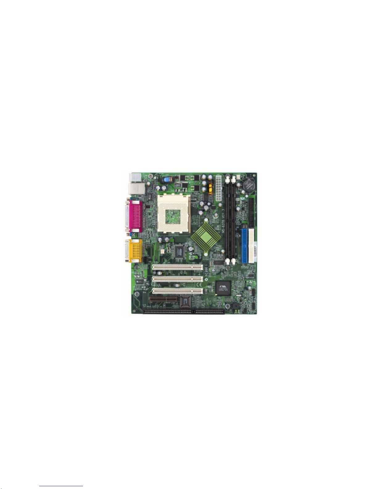
MSI MS-6378 User manual
i
Version 3.1
G52-MA00585
MS-6378 (v3.X) Micro-ATX Mainboard
MSI
MICRO-STAR INTERNATIONAL
ii
Manual Rev: 3.1
Release Date: Mar. 2002
FCC-BRadioFrequencyInterferenceStatement
This equipment has been tested and found to comply with the limits for a class
B digital device, pursuant to part 15 of the FCC rules. These limits are designed
to provide reasonable protection against harmful interference when the equip-
ment is operated in a commercial environment. This equipment generates, uses
and can radiate radio frequency energy and, if not installed and used in accor-
dance with the instruction manual, may cause harmful interference to radio
communications. Operation of this equipment in a residential area is likely to
cause harmful interference, in which case the user will be required to correct
the interference at his own expense.
Notice 1
The changes or modifications not expressly approved by the party respon-
sible for compliance could void the user’s authority to operate the equipment.
Notice 2
Shielded interface cables and A.C. power cord, if any, must be used in order to
comply with the emission limits.
VOIR LA NOTICE D’INSTALLATION AVANT DE RACCORDER AU
RESEAU.
Micro-StarInternational MS-6378
Testedtocomply
withFCCStandard
ForHomeorOfficeUse

iii
Edition
Mar.2002
Copyright Notice
The material in this document is the intellectual property of MICRO-STAR
INTERNATIONAL. We take every care in the preparation of this document,
but no guarantee is given as to the correctness of its contents. Our products
are under continual improvement and we reserve the right to make changes
without notice.
Trademarks
All trademarks are the properties of their respective owners.
AMD, Athlon and Duron are registered trademarks of AMD Corporation.
PS/2 and OS®/2 are registered trademarks of International Business Machines
Corporation.
Windows®95/98/2000/NT/ME/XP are registered trademarks of Microsoft
Corporation.
Netware®is a registered trademark of Novell, Inc.
Award®is a registered trademark of Phoenix Technologies Ltd.
AMI®is a registered trademark of American Megatrends Inc.
Revision History
Revision RevisionHistory Date
3.1 Add JWOL1, JMDM1, JCASE1 Mar.2002

iv
1. Always read the safety instructions carefully.
2. Keep this User’s Manual for future reference.
3. Keep this equipment away from humidity.
4. Lay this equipment on a reliable flat surface before setting it up.
5. The openings on the enclosure are for air convection hence protects the
equipmentfromoverheating. DONOTCOVERTHEOPENINGS.
6. Make sure the voltage of the power source and adjust properly 110/220V
before connecting the equipment to the power inlet.
7. Place the power cord such a way that people can not step on it. Do not
place anything over the power cord.
8. Always UnplugthePower Cordbeforeinserting any add-oncardor module.
9. All cautions and warnings on the equipment should be noted.
10. Never pour any liquid into the opening that could damage or cause electri-
cal shock.
11. If any of the following situations arises, get the equipment checked by a
service personnel:
zThe power cord or plug is damaged
zLiquid has penetrated into the equipment
zThe equipment has been exposed to moisture
zThe equipment has not work well or you can not get it work according
to User’s Manual.
zThe equipment has dropped and damaged
zIf the equipment has obvious sign of breakage
12. DO NOT LEAVE THIS EQUIPMENT IN AN ENVIRONMENT
UNCONDITIONED,STORAGETEMPERATUREABOVE600C(1400F),IT
MAYDAMAGETHEEQUIPMENT.
Safety Instructions
CAUTION: Danger of explosion if battery is incorrectly replaced.
Replace only with the same or equivalent type recommended by the
manufacturer.

v
CONTENTS
Chapter1.GettingStarted ........................................................................ 1-1
Mainboard Specification ......................................................................1-2
Mainboard Layout ...............................................................................1-4
Quick Components Guide ....................................................................1-5
Chapter2.HardwareSetup ....................................................................... 2-1
Central Processing Unit: CPU ..............................................................2-2
CPU Installation Procedures .........................................................2-2
CPU Core Speed Derivation Procedure .........................................2-4
CPU ClockSelection ......................................................................2-4
Memory................................................................................................2-5
Introduction to SDRAM ...............................................................2-5
DIMM Module Combination......................................................... 2-6
Installing DIMM Modules ............................................................ 2-6
Power Supply .......................................................................................2-7
ATX 20-Pin Power Connector: JPWR1 ..........................................2-7
BackPanel ............................................................................................2-8
Mouse Connector ......................................................................... 2-8
Keyboard Connector .....................................................................2-9
USB Connectors ............................................................................ 2-9
Serial Port Connector: COM A .................................................... 2-10
VGA DB 15 Pin Connector .......................................................... 2-10
Parallel Port Connector: LPT1...................................................... 2-11
LAN(RJ-45)Jack(Optional) ........................................................ 2-12
Joystick/Midi Connector ............................................................. 2-12
Audio Port Connectors ............................................................... 2-12
Connectors......................................................................................... 2-13
Floppy Disk Drive Connector: FDD1........................................... 2-13
Hard Disk Connectors: IDE1 & IDE2 ........................................... 2-14
Fan Power Connectors: C_FAN1/S_FAN1 .................................. 2-15

vi
IrDA Infrared Module Header: JIR1 ............................................ 2-16
CD-InConnector:JCD1 ............................................................... 2-16
Front Panel Connectors: JFP1 & JFP2 ......................................... 2-17
Front Panel Audio Connector: JAUD2 ........................................ 2-18
Front USB Connector: JUSB1...................................................... 2-19
Chassis Intrusion Switch Connector: JCASE1 ............................ 2-19
Wake On Ring Connector: JMDM1............................................. 2-20
Wake On LAN Connector: JWOL1.............................................. 2-20
Jumpers .............................................................................................. 2-21
Clear CMOSJumper: JBAT1 ........................................................ 2-21
CPU ClockSelection Jumper: JFSB1 ............................................ 2-22
Slots ................................................................................................... 2-23
PCI Slots ...................................................................................... 2-23
CNR(CommunicationNetwork Riser) Slot .................................. 2-23
ISA Slot (Optional) ...................................................................... 2-23
PCI Interrupt Request Routing .................................................... 2-24
Chapter3.BIOSSetup.............................................................................. 3-1
Entering Setup......................................................................................3-2
Control Keys ................................................................................. 3-2
Getting Help ..................................................................................3-3
The Main Menu ...................................................................................3-4
Standard CMOS Features ....................................................................3-6
Advanced BIOS Features ....................................................................3-8
Advanced Chipset Features............................................................... 3-12
Integrated Peripherals ........................................................................ 3-16
Power Management Setup ................................................................. 3-21
PnP/PCI Configurations ..................................................................... 3-26
PC Health Status ................................................................................ 3-29
Frequency/Voltage Control ................................................................ 3-30
LoadFail-Safe/OptimizedDefaults ..................................................... 3-31

vii
Set Supervisor/User Password........................................................... 3-32
Glossary ....................................................................................................G-1

Getting Started
1-1
Chapter 1. Getting Started
Thank you for purchasing the MS-6378 (v3.X) Micro-ATX mainboard.
The MS-6378 (v3.X) is a high-performance computer mainboard based on VIA®
Apollo KLE133 (VT8361+VT82C686B) chipset for optimal system efficiency.
Designed to fit the advanced AMD®Athlon™, Athlon™ XP and Duron™
processors in the 462 pin package, the motherboard provides an inexpensive
and professional desktop platform solution.
1
Getting Started
TOPICS
Mainboard Specification 1-2
Mainboard Layout 1-4
Quick Components Guide 1-5

Chapter 1
1-2
CPU
Supports Socket 462 for AMD®Duron™/Athlon™ /Athlon™ XP proces-
sors
Supports Athlon XP 1900+ MHz and higher processor
Chipset
VIA®VT8361 chipset (552 BGA)
- FSB @200/266MHz
- Integrated Trident Blade 2D/3D video accelerator
- PCI advanced high performance memory controller
- Supports PC100/133 SDRAM, VCM & ESDRAM technology
VIA®VT686B chipset (352 BGA)
- Enhanced Power Management Features
- Integrated Super I/O (FDC, LPT, COM 1/2 and IR)
- Dual bus Master IDE Ultra DMA 33/66/100
- Integrated Hardware Soundblaster
- Direct Sound AC97 Audio
- ACPI
Clock Generator
Supports 100/133MHz clocks
MainMemory
Supports four memory banks using 168-pin unbuffered DIMM
Supports a maximum memory size of 1GB (256 MB DRAM technology)
Supports 3.3V SDRAM DIMM
Slots
Three 32-bit Master PCI Bus slots (support 3.3V/5V PCI bus interface)
One CNR (Communication Network Riser) slot
One ISA slot (optional)
On-BoardIDE
An IDE controller on the VIA®VT82C686B chipset provides IDE HDD/CD-
ROM with PIO, Bus Master and Ultra DMA 33/66/100 operation modes
Can connect up to four IDE devices
Mainboard Specification

Getting Started
1-3
On-Board Peripherals
On-Board Peripherals include:
- 1 floppy port supports 2 FDDs with 360K, 720K, 1.2M, 1.44M and
2.88Mbytes
- 1 serial port (COM A)
- 1 parallel port supports SPP/EPP/ECP mode
- 4 USB ports (Rear * 2/ Front * 2)
- 1 IrDA connector for SIR/CIR/FIR/ASKIR/HPSIR
- 1 VGA port
- 1 Audio/Game port
Network(Optional)
ADMtek AN983B
Audio
Audio controller integrated in 686B chipset
Software audio codec Realtek ALC101T
- Onboard Front Audio Pin Header
BIOS
The mainboard BIOS provides “Plug & Play” BIOS which detects the pe-
ripheral devices and expansion cards of the board automatically.
The mainboard provides a Desktop Management Interface (DMI) function
which records your mainboard specifications.
Dimension
Micro-ATX Form Factor: 24.4 cm (L) x 21.5 cm (W)
Mounting
6 mounting holes
Others
Suspend to Disk S4/S3
Plug and Play function
Supports PCI 2.2
Hardware Monitoring (optional)
Modem (External/Internal) Ring Wake up Function
LAN Wake up Function
Other manuals for MS-6378
2
Table of contents
Other MSI Motherboard manuals


MSI
MSI A88X-G45 GAMING User manual

MSI
MSI MS-6217 Series User manual

MSI
MSI PRO B650-S WIFI User manual

MSI
MSI MS-6526 Manual

MSI
MSI X58 PRO MS-7522 User manual

MSI
MSI A68HM User manual

MSI
MSI K8MM3 Series User manual

MSI
MSI MPG Z390 GAMING PLUS User manual

MSI
MSI Z170A KRAIT GAMING User manual

MSI
MSI MAG B560M BAZOOKA User manual












