MSI 694T Pro User manual

v
Contents
Chapter 1. Introduction ...............................................................1-1
MainboardSpecification ............................................................1-2
MainboardLayout .....................................................................1-4
Quick Components Guide .........................................................1-5
Key Features ............................................................................1-6
MSI Special Features................................................................1-7
T.O.P Tech™ ......................................................................1-7
PC Alert™ III .......................................................................1-8
D-LED™ & D-Bracket™....................................................1-10
Fuzzy Logic™ III ...............................................................1-12
Chapter 2. Hardware Setup ........................................................2-1
Central Processing Unit: CPU ...................................................2-2
CPU Installation Procedures ...............................................2-2
CPUCoreSpeedDerivationProcedure................................2-3
Memory Installation...................................................................2-4
Module Installation Procedures ...........................................2-5
Power Supply............................................................................2-6
ATX 20-Pin Power Supply....................................................2-6
Back Panel ...............................................................................2-7
MouseConnector................................................................2-7
KeyboardConnector ...........................................................2-8
USB Connectors .................................................................2-8
Parallel Port Connector .......................................................2-9
Serial Port Connector: COM A & COM B ..........................2-10
Joystick/Midi Connectors ..................................................2-10
Audio Port Connectors ......................................................2-10
Connectors ............................................................................. 2-11
Floppy Disk Drive Connector: FDD1 .................................. 2-11
Hard Disk Connectors: IDE1 & IDE2 .................................2-12

vi
Case Connector: JFP1 ......................................................2-13
Power Switch....................................................................2-13
Reset Switch ....................................................................2-13
PowerLED........................................................................2-13
Speaker ............................................................................2-14
HDDLED ..........................................................................2-14
Wake On Ring Connector: JMDM1 ...................................2-15
Wake On LAN Connector: JWOL1 ....................................2-15
IrDAInfraredModuleConnector:J4 ...................................2-16
Modem-InConnector: MODEM_IN ....................................2-16
CD-InConnector:CD_IN ...................................................2-17
AuxLine-InConnector:AUX_IN .........................................2-17
Fan Power Connectors: CPUFAN/SYSFAN.......................2-18
USB PC To PC Connector: USB2 (Optional) .....................2-19
D-Bracket™ Connector: JDLED ........................................2-22
Jumpers ..................................................................................2-23
Clear CMOS Jumper: JBAT1 .............................................2-23
Slots .......................................................................................2-24
AGP (Accelerated Graphics Port) Slot ..............................2-24
AMR (Audio Modem Riser) Slot ........................................2-24
PCI Slots ..........................................................................2-24
ISA Slot ............................................................................2-25
PCI Interrupt Request Routing ...........................................2-25
Chapter 3. AMI® BIOS Setup......................................................3-1
Entering Setup ..........................................................................3-2
Control Keys .............................................................................3-2
Getting Help..............................................................................3-3
The Main Menu .........................................................................3-4
Standard CMOS Features .........................................................3-6
AdvancedBIOS Features ..........................................................3-8

vii
Advanced Chipset Features .................................................... 3-11
Power Management Setup ......................................................3-15
PNP/PCIConfigurations ..........................................................3-19
IntegratedPeripherals .............................................................3-21
HardwareMonitorSetup..........................................................3-25
Load Optimized/Fail-Safe Defaults ..........................................3-27
Supervisor/UserPassword ......................................................3-29
IDE HDD AUTO Detection .......................................................3-31
Save & Exit Setup...................................................................3-32
Exit Without Saving.................................................................3-33
Chapter 4. Award® BIOS Setup .................................................4-1
Entering Setup ..........................................................................4-2
Control Keys .............................................................................4-2
Getting Help..............................................................................4-3
The Main Menu .........................................................................4-4
Standard CMOS Setup .............................................................4-6
AdvancedBIOS Features ..........................................................4-8
Advanced Chipset Features ....................................................4-12
IntegratedPeripherals .............................................................4-15
Power Management Setup ......................................................4-19
PnP/PCI Configuration Setup ..................................................4-25
PC Health Status ....................................................................4-27
Frequency/Voltage Control.....................................................4-28
Load Fail-Safe/Optimized Defaults ..........................................4-29
Chapter 5. Installing Drivers .......................................................5-1
Overview....................................................................................5-2
System Requirements ........................................................5-2
Driver Installation for Windows® 98SE ......................................5-3
Driver Installation for Windows® 2000 .......................................5-5
Driver Installation for Windows® ME..........................................5-7

viii
Driver Installation for Windows® NT4.0 ......................................5-9
Appendix A: USB PC to PC Networking Function..................... A-1
Installing GeneLink™ LAN Driver.............................................. A-2
Using USB PC to PC Networking Function .............................. A-4
Glossary............................................................................................ I

Introduction
1-1
Chapter 1.
Introduction 1
The 694T Pro (MS-6309 v5.X) ATX mainboard is a high-performance
computer mainboard based on VIA®Apollo Pro133T chipset. The 694T Pro
(MS-6309 V5.X) is optimized to support the whole series of new generation
Intel®Pentium®III (FC-PGA/FC-PGA2) processor for high-end business/
personal desktop market.
The Apollo Pro133T chipset consists of the VT82C694T North
Bridge and the VT82C686B South Bridge. The VT82C694T is a Socket-370
system logic north bridge with the addition of 133 MHz capability for both
the CPU and SDRAM interfaces. It may be used to implement desktop
computer systems from 66MHz to 133MHz based on Socket-370. The
primary features of the VT82C694T are: Socket-370 CPU (Front Side Bus)
Interface (66 / 100 / 133MHz), DRAM Memory Interface (66 / 100 / 133MHz),
AGP Bus Interface (66MHz), PCI Bus Interface (33MHz).
TheVT82C686BPSIPC (PCI Super-I/O Integrated Peripheral
Controller) is a high integration, high performance, power-efficient, and high
compatibility device that supports Intel and non-Intel based processor to
PCI bus bridge functionality to make a complete Microsoft PC99-compliant
PCI/ISA system.
This chapter includes the following topics:
Mainboard Specification 1-2
Mainboard Layout 1-4
Quick Components Guide 1-5
Key Features 1-6
MSI Special Features 1-7

Chapter 1
1-2
CPU
zSupports Socket 370 for whole series of new generation of Intel®
Celeron™ / Pentium III (FC-PGA)/(FC-PGA2) and VIA®C3 processors
zSupports500MHz,550MHz,600MHz,633MHz,667MHz,700MHz,
733MHz,800MHz,866MHz,933MHz,1GHz,1.1GHz,1.13GHzandupto
1.2GHz
Chipset
zVIA®694T chipset (520 BGA)
-Supports66/100/133MHzFSB
- AGP 4x and PCI plus Advanced ECC Memory Controller
- Supports PC100/133 SDRAM, VCM & ESDRAM technology
zVIA®VT82C686Bchipset(352BGA)
- Enhanced Power Management Features
- Integrated Super I/O (FDC, LPT, COM 1/2, and IR)
- DirectSound AC97 Audio
- Integrated hardware Soundblaster
- Dual bus Master IDE Ultra DMA33/66/100
-ACPI
Clock Generator
z66/100/133MHz clocks are supported.
Main Memory
zSupports six memory banks using three 168-pin unbuffered DIMM
zSupportsamaximummemorysizeof 1.5GB (32M x8)
zSupports 3.3v SDRAM DIMM
Slots
zOne AGP (Accelerated Graphics Port) slot
- AGP specification compliant
- SupportsAGP1x/2x/4x
zOne AMR (Audio Modem Riser) slot
zFive 32-bit Master PCI Bus slots and one 16-bit ISA bus slots
zSupports 3.3v/5v PCI bus Interface
Mainboard Specification

Introduction
1-3
On-Board IDE
zAn IDE controller on the VIA®VT82C686B chipset provides IDE HDD/
CD-ROM with PIO, Bus Master and Ultra DMA 33/66/100 operation
modes.
zCan connect up to four IDE devices
On-Board Peripherals
zOn-Board Peripherals include:
- 1 floppy port supports 2 FDDs with 360K, 720K, 1.2M, 1.44M and
2.88Mbytes.
- 2 serial ports (COMA + COMB)
- 1 parallel port supports SPP/EPP/ECP mode
- 4 USB ports (Rear x 2 / Front x 2)
- 1 IrDA/HP connector for SIR
- D-Bracket pin header
Audio
zChip integrated
zCreative CT5880 Hardware Audio (optional)
BIOS
zThe mainboard BIOS provides “Plug & Play” BIOS which detects the
peripheral devices and expansion cards of the board automatically.
zThe mainboard provides a Desktop Management Interface (DMI) func-
tion which records your mainboard specifications.
Dimension
zATX Form Factor: 30.5cm (L) x 19.2cm (W) x 4 layers PCB
Mounting
z6 mounting holes
Chapter 1
1-4
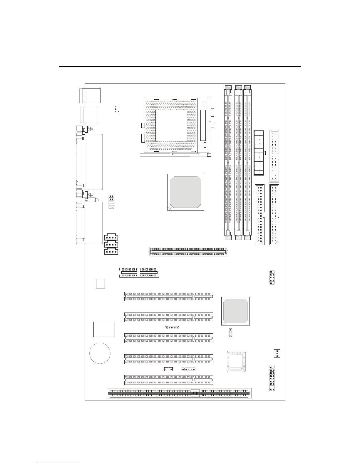
Mainboard Layout
MS-6309 (V5.X) ATX VA Mainboard
AGP Slot
BATT
+
VT82C
686B
VIA
694T
ATXPowerSupply
JFP1
BIOS
PCI Slot 1
PCI Slot 3
PCI Slot 2
PCI Slot 4
PCI Slot 5
IDE1
IDE2
DIMM2
DIMM3
DIMM1
USB Ports
Top :
Parallel Port
Bottom:
COM A
COM B
Top : mouse
Bottom:
keyboard
CD_IN
MODEM_IN
AUX_IN
Top :
Game port
Bottom:
Line-Out
Line-In
Mic
SOCKET370
FDD
AMR Slot
Creative
CT5880
(Optional)
Codec USB2
JDLED
CPUFAN
SYSFAN
JMDM1
JWOL1
J4
JBAT1
D-LED
ISA Slot

Introduction
1-5
Quick Components Guide
Component Function Reference
DIMM1~2 Installing SDRAM modules See p. 2-4~2-5
Socket 370 Installing CPU See p. 2-2
CPUFAN Connecting to CPUFAN See p. 2-18
SYSFAN Connecting to SYSTEM FAN See p. 2-18
ATX Power Supply Installing power supply See p. 2-6
IDE1& IDE2 Connecting to IDE hard disk drive See p.2-12
FDD1 Connecting to floppy disk drive See p.2-11
USB2 Connecting to USB interface See p. 2-19
PCI Slot 1~5 Installing PCI expansion cards See p. 2-24
AGP Slot Installing AGP cards See p. 2-24
AMR Slot Installing AMR riser cards See p. 2-24
ISA Slot Installing ISA expansion card See p. 2-25
JMDM1 Connecting to modem module See p. 2-15
JWOL1 Connecting to LAN card See p. 2-15
JBAT1 Clearing CMOS data See p. 2-23
JFP1 Connecting to case See p. 2-13
J4 Connecting to IR module See p. 2-16
JDLED Connecting to D-Bracket™ See p. 2-22

Chapter 1
1-6
zATX Form Factor
zCPU: Socket 370 for Intel®Celeron™/Pentium III (FC-PGA/FC-PGA2)
family series and VIA®C3 Processors
zMemory:3PC100/PC133 SDRAMDIMMs
zVi/o & Vcore Adjustable
zUSB PC to PC Networking Function (Optional)
zSupportOptionalD-Bracket™
zSlot: 1 AGP slot, 1 AMR slot, 5 PCI slots, 1 ISA slot
zI/O: 2 serial ports, 1 parallel port, 4 USB ports, 1 floppy port, 1 IrDA
connector, 1 Audio/Game port
zSupport PCI 2.2
zAudio: Chip integrated
zLAN Wake up Function
zModem (Internal) Ring Wake up Function
zD-LED™ -- 4 LEDs embedded in the mainboard
zT.O.P. TechTM -- Thermal Overheat Protection Technology
zPC AlertTM III system hardware monitor
zFuzzy Logic™ III overclocking utility
Key Features
This manual suits for next models
1
Table of contents
Other MSI Motherboard manuals

MSI
MSI K8N Neo Platinum User manual

MSI
MSI MS-7721 User manual

MSI
MSI MICRO ATX EX7 User manual

MSI
MSI Z490 -S01 User manual

MSI
MSI MS-6787 User manual

MSI
MSI 970A-G43 Series User manual

MSI
MSI Z77A-G41 Series User manual

MSI
MSI B560M PRO User manual

MSI
MSI 880GM-E41 series User manual

MSI
MSI Z270 SLI PLUS User manual

MSI
MSI B150A GAMING PRO User manual

MSI
MSI C847MS-E33 Series User manual

MSI
MSI MS-6135 User manual

MSI
MSI AM1M Series User manual

MSI
MSI MS-6163VA User manual

MSI
MSI 845 PRO4 User manual

MSI
MSI 610BF User manual

MSI
MSI MS-6114 User manual

MSI
MSI P6N Ultra Series User manual

MSI
MSI MEG X670E GODLIKE User manual


