Graco 750 Series User manual

Instructions – Parts List
GRACO INC.ąP.O. BOX 1441ąMINNEAPOLIS, MNą55440-1441
Copyright 2001, Graco Inc. is registered to I.S. EN ISO 9001
Series 750 Hose Reel
Model 245410, Series C
This reel is not to be used for overhead mount applications.
Low Pressure Fuel Dispense Reel: 375 psi (2.59 MPa, 25.9 bar) Maximum Working Pressure
309442 rev.E
Read warnings and instructions.
TI1619c
Parts

2 309442E
Table of Contents
Warnings 3. . . . . . . . . . . . . . . . . . . . . . . . . . . . . . . . . . .
Installation
Typical Layout 5. . . . . . . . . . . . . . . . . . . . . . . . . . . . . . . . .
Installing a Hose 6. . . . . . . . . . . . . . . . . . . . . . . . . . . . . . .
Adjusting Spring Tension 7. . . . . . . . . . . . . . . . . . . . . . . .
Maintenance
Pressure Relief Procedure 8. . . . . . . . . . . . . . . . . . . . . . .
Replacing the Service Hose 8. . . . . . . . . . . . . . . . . . . . . .
Oiling the Hose Rollers 9. . . . . . . . . . . . . . . . . . . . . . . . . .
Service
Swivel 10. . . . . . . . . . . . . . . . . . . . . . . . . . . . . . . . . . . . . . .
Spring Canister 11. . . . . . . . . . . . . . . . . . . . . . . . . . . . . . .
Reel Ratchet and Dog 11. . . . . . . . . . . . . . . . . . . . . . . . .
Parts Drawing 12. . . . . . . . . . . . . . . . . . . . . . . . . . . . .
Parts List 13. . . . . . . . . . . . . . . . . . . . . . . . . . . . . . . . . .
Technical Data 14. . . . . . . . . . . . . . . . . . . . . . . . . . . .
Dimensions 15. . . . . . . . . . . . . . . . . . . . . . . . . . . . . . .
Graco Standard Warranty 16. . . . . . . . . . . . . . . .
Graco Information 16. . . . . . . . . . . . . . . . . . . . . . . .

309442E 3
Symbols
Warning Symbol
WARNING
This symbol alerts you to the possibility of serious
injury or death if you do not follow the instructions.
Caution Symbol
CAUTION
This symbol alerts you to the possibility of damage to
or destruction of equipment if you do not follow the
instructions.
EQUIPMENT MISUSE HAZARD
Equipment misuse can cause the equipment to rupture or malfunction and result in serious injury.
DThis equipment is for professional use only.
DRead all instruction manuals, tags, and labels before operating the equipment.
DUse the equipment only for its intended purpose. If you are not sure, call your Graco distributor.
DDo not alter or modify this equipment. Use only genuine Graco parts and accessories. Modifying
parts can cause a malfunction and result in serious bodily injury.
DCheck equipment daily. Repair or replace worn or damaged parts immediately.
DDo not exceed the maximum working pressure of the lowest rated system component. Refer to
the Technical Data on page 14 for the maximum working pressure of this equipment.
DUse fluids and solvents that are compatible with the equipment wetted parts. Refer to the Tech-
nical Data section of all equipment manuals. Read the fluid and solvent manufacturer’s warn-
ings.
DDo not use hoses to pull equipment.
DRoute hoses away from traffic areas, sharp edges, moving parts, and hot surfaces. Do not
expose hoses to temperatures above 82_C (180_F) or below –40_C (–40_F).
DDo not lift pressurized equipment.
DComply with all applicable local, state, and national fire, electrical, and safety regulations.
DIf you are adding a service hose and dispensing valve to a bare hose reel, be sure you know the
maximum working pressure of all the components.
INSTRUCTIONS
WARNING

4 309442E
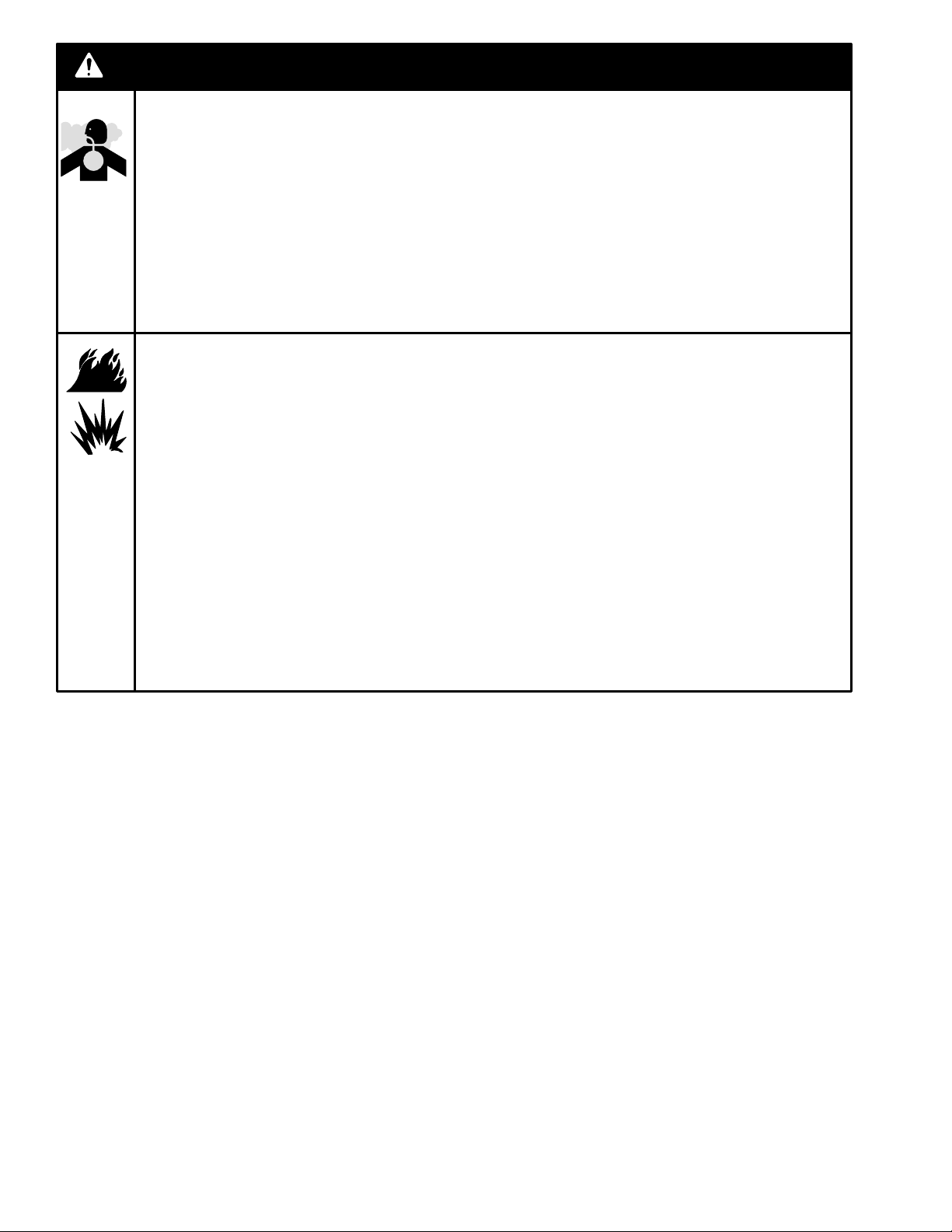
TOXIC FLUID HAZARD
Hazardous fluid or toxic fumes can cause serious injury or death if inhaled, swallowed, splashed in
the eyes, or splashed on the skin.
DKnow the specific hazards of the fluid you are using.
DStore hazardous fluid in an approved container. Dispose of hazardous fluid according to all
local, state and national guidelines.
DAlways wear protective eyewear, gloves, clothing, and a respirator as recommended by the fluid
and solvent manufacturer.
FIRE AND EXPLOSION HAZARD
Improper grounding, poor ventilation, open flames, or sparks can cause a hazardous condition and
result in a fire or explosion and serious injury.
DBe sure the entire fluid system is properly grounded. The hoses installed with these hose reels
must be electrically conductive. The hose reel is grounded by connecting electrically conductive
supply hoses to a properly grounded system. Refer to your pump instruction manual for com-
plete details.
DIf there is any static sparking or you feel an electric shock while using this equipment, stop
dispensing immediately. Do not use the equipment until you identify and correct the problem.
DProvide fresh air ventilation to avoid the buildup of flammable fumes from solvents or the fluid
being dispensed.
DKeep the dispensing area free of debris, including solvent, rags, and spilled gasoline.
DDo not smoke while dispensing flammable fluids.
WARNING

309442E 5
Installation–Typical Layout
The installation shown in Fig.1 is only a guide for
selecting and installing a hose reel system. The
components and accessories shown are the minimum
requirements for all systems; however, it is not an
actual system design. Contact your Graco distributor
for assistance in designing a system to suit your
needs.
WARNING
Never allow the reel to spin freely. Doing so
causes the hose to spin out of control, which could
cause serious injury if you are hit by the hose.
CAUTION
A flexible hose connection must be used between
the hose reel inlet and the source of supply to pre-
vent possible misalignment and binding.
WARNING
This hose reel is intended for floor-mounted
applications only. Do not install this reel in an
overhead mounting.
KEY
A Main air supply line
B Pump air supply line
C Air filter
D Air regulator
E Bleed-type master air valve (required)
F Pump
G Pump grounding wire (required)
H Thermal relief valve (required)
J Dump valve (required)
K Fluid shut–off valve
M Hose reel
N Dispensing valve
P Mounting channel/base
Q Flexible inlet hose
R Pressure relief valve (required to limit fluid outlet
pressure to 50 psi [350 kPa, 3.5 bar])
Fig. 1
NOTE: Parts are not proportional.
1Fluid from the relief valve (R) must be
vented to a safe area.
H
B
A
CDE
F
G
J
P
K
Q
M
N
R
1
TI1622d

6 309442E
Installation–Hose
To install a hose on a hose reel with the proper amount
of spring tension, follow these steps:
WARNING
Improper grounding can cause a hazardous
condition and may result in fire or explosion and
serious injury. The hoses installed with this reel
must be electrically conductive.
WARNING
Always wear heavy, non-slippery gloves when
adjusting the spring tension to protect your hands
from being cut on the hose reel.
1. Clamp the hose reel to a flat surface.
2. Place a piece of tape on the side of the reel flange
as a visual reference point for counting reel rota-
tions.
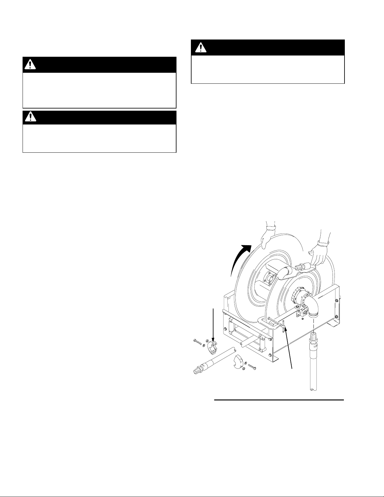
3. Unlatch the reel drum, and allow it to slowly rotate
until all spring tension has been released. Then
rotate the reel in the direction of the arrow shown
in Fig. 2 to achieve the proper amount of spring
tension for the hose you are installing, approxi-
mately 14–15 turns.
NOTE: Release the reel only at points where it is
securely latched.
4. Attach a C-clamp to the reel flange, as shown in
Fig. 2, to help prevent the reel from unintentionally
becoming unlatched and spinning freely.
WARNING
Never allow the reel to spin freely. Doing so
causes the hose to spin out of control, which could
cause serious injury if you are hit by the hose.
5. Uncoil and extend the new hose, and loosely
install the hose stop (25) near the outlet end of the
hose.
6. Attach the other end of the new hose to the
90-degree elbow.
7. Remove the C-clamp from the reel flange.
8. Pull the hose firmly enough to release the latch,
then slowly allow the hose to retract.
9. Ensure that the hose can be pulled out all the way
and that it fully retracts. If it does not pull out or
retract properly, see Adjusting Spring Tension
on page 7.
10. Position the hose stop (25) so that the hose ex-
tends far enough for all operators to reach the
dispensing valve.
Fig. 2
25
C-clamp
ti1625d

309442E 7
Installation–Adjusting Spring Tension
If the hose cannot be pulled out all the way, or if it does
not retract all the way back onto the hose reel, you
need to adjust the spring tension. To do so, follow
these steps:
WARNING
Always wear heavy, non-slippery gloves when
adjusting the spring tension to protect your hands
from being cut on the hose reel.
1. Pull the hose out and engage the latch.
2. Remove the dispensing valve (not shown) and the
hose stop (25). See Fig. 3.
3. Pull the loose end of the hose back in through the
hose rollers, and manually wrap the hose onto the
reel.
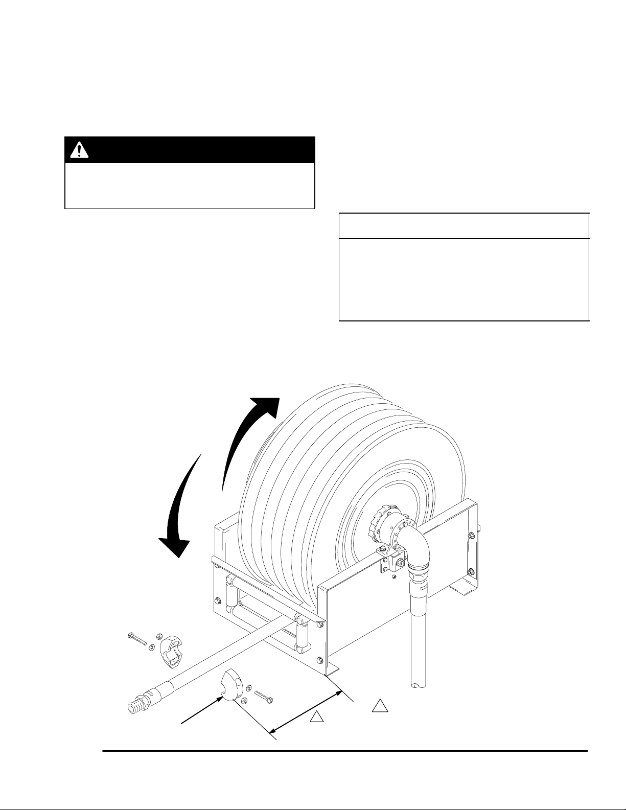
4. Rotate the reel in the direction of the appropriate
arrow shown in Fig. 3, keeping the hose wrapped
on the reel. Each rotation of the reel increases or
decreases enough spring tension to retract or let
out approximately 5 ft (1.5 m) of hose.
5. Check the spring tension. The hose must pull out
fully and retract fully.
6. Repeat Steps 4 and 5 until you have the proper
amount of spring tension.
CAUTION
Do not increase the spring tension so much that the
spring winds up tightly before the hose is fully
extended. A spring that is wound too tightly stops
the reel from rotating before the hose is fully ex-
tended, which puts excessive strain on the hose and
reel spring and could damage the reel.
7. Reroute the hose through the hose rollers, and
reinstall the hose stop and dispensing valve.
Fig. 3
25
1Position hose stop (25) within operator’s reach.
1
increase
tension
decrease
tension
TI1624c

8 309442E
Maintenance
Pressure Relief Procedure
WARNING
The system pressure must be manually relieved to
prevent the system from dispensing accidentally.
To reduce the risk of an injury from injection,
splashing fluid, or moving parts, follow the Pres-
sure Relief Procedure whenever you
DAre instructed to relieve the pressure
DStop dispensing
DCheck or service any of the system equipment
DInstall or clean the dispensing valve
1. Close the supply pump’s bleed-type master air
valve (required in pneumatic systems).
2. Open the dispensing valve until pressure is fully
relieved.
3. Open the dump valve at the pump fluid outlet, and
leave it open until you are ready to use the system
again.
If you suspect that the dispensing valve or extension is
clogged or that pressure has not been fully relieved
after following all the steps above, very slowly loosen
the coupler or hose end coupling, and allow pressure
to be relieved gradually, then loosen the part com-
pletely. Then clear the clog.
Replacing the Service Hose
WARNING
To reduce the risk of serious injury whenever you
are instructed to relieve pressure, always follow
the Pressure Relief Procedure at left.
1. Relieve the pressure if you are replacing the
service hose on a reel that is already truck-
mounted. Then go to Step 3. Otherwise, start at
Step 2.
2. Clamp the hose reel to a flat surface if you are
replacing the service hose on a reel that is not
mounted anywhere.
3. Fully extend the hose and latch the reel.
4. Attach a C-clamp to the reel flange to help prevent
the reel from unintentionally becoming unlatched
and spinning freely. See Fig. 4.

309442E 9
Maintenance
WARNING
Never allow the reel to spin freely. Doing so
causes the hose to spin out of control, which could
cause serious injury if you are hit by the hose.
5. Disconnect the service hose from the 90-degree
elbow, and remove it.
6. Uncoil and extend the new hose, and install the
hose stop (25) near the outlet end of the hose.
7. Attach the other end of the new hose to the
90-degree elbow.
8. Remove the C-clamp from the reel flange.
9. Pull the hose firmly enough to release the latch,
then slowly allow the hose to retract.
10. Position the hose stop (25) so the hose extends
far enough for all operators to reach the dispens-
ing valve.
Fig. 4
25
C-clamp
TI1625e
Oiling the Hose Rollers
Every six months, apply one or two drops of light
motor oil to lubricate the hose reel at point A. See
Fig. 5.
Fig. 5
A
A
TI1626A

10 309442E
Service
Swivel and Bearings
WARNING
To reduce the risk of serious injury whenever you
are instructed to relieve pressure, always follow
the Pressure Relief Procedure at left.
1. Relieve the pressure.
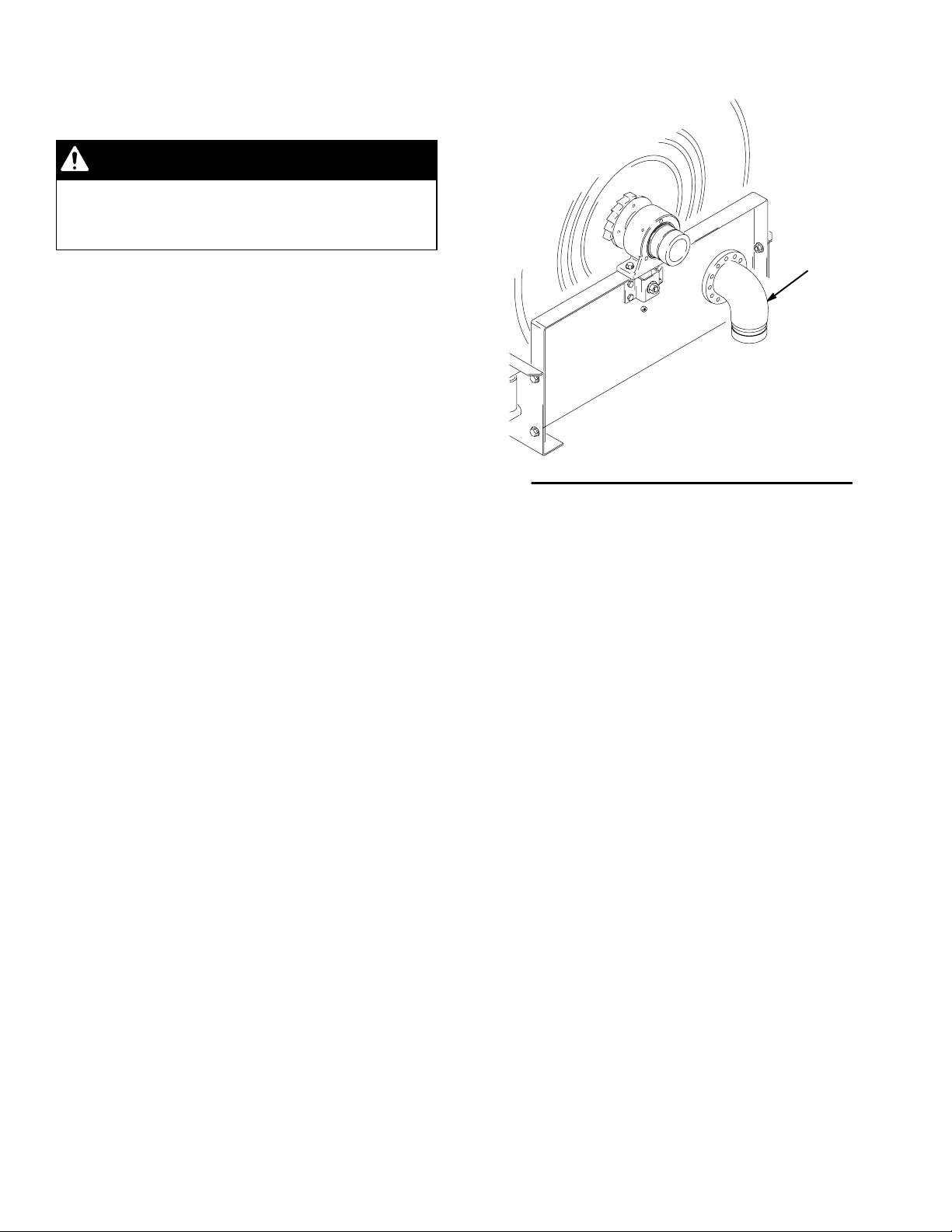
2. Remove the 90_inlet adapter (24) (see Fig. 6).
3. Lubricate the shaft and bearing surfaces with
high-quality grease. Bearings are fitted with grease
zerks and require periodic lubrication.
4. Install the parts as shown in Fig. 6. Fig. 6
TI1628c
24
This manual suits for next models
2
Table of contents
Other Graco Tools manuals

Graco
Graco 258853 Operating instructions

Graco
Graco 17Y907 Instruction Manual

Graco
Graco 24M510 Owner's manual

Graco
Graco SD Series Use and care manual

Graco
Graco LD Series User manual

Graco
Graco LD Series User manual

Graco
Graco LDX Series Use and care manual

Graco
Graco XD40 User manual

Graco
Graco XD30 Series User manual

Graco
Graco SD 10 Series User manual

Graco
Graco 24N719 User manual

Graco
Graco SDX Series User manual

Graco
Graco SD Series User manual

Graco
Graco 223-440 Operation manual

Graco
Graco SD Series User manual

Graco
Graco 17R720 User manual

Graco
Graco 17J866 User manual

Graco
Graco 241105 Operation manual

Graco
Graco 257815 User manual

Graco
Graco 25F130 User manual