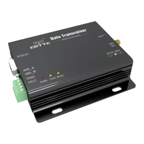
Ebyte E830-DTU(2R2-433L)-V8 User manual

Digital/Switching Wireless data radio
E830-DTU(2R2-433L)-V8

Chengdu Ebyte Electronic Technology Co.,Ltd E830-DTU(2R2-433L)-V8 User Manual
Copyright ©2012–2021,Chengdu Ebyte Electronic Technology Co.,Ltd.
Disclaimer
EBYTE reserves all rights to this document and the information contained herein.
Products, names, logos and designs described herein may in whole or in part be
subject to intellectual property rights. Reproduction, use, modification or disclosure to
third parties of this document or any part thereof without the express permission of
EBYTE is strictly prohibited.
The information contained herein is provided “as is” and EBYTE assumes no
liability for the use of the information. No warranty, either express or implied, is given,
including but not limited, with respect to the accuracy, correctness, reliability and
fitness for a particular purpose of the information. This document may be revised by
EBYTE at any time. For most recent documents, visit www.ebyte.com.

Chengdu Ebyte Electronic Technology Co.,Ltd E830-DTU(2R2-433L)-V8 User Manual
1
Contents
Disclaimer .......................................................................................................................................................................2
Chapter 1 Product Introduction ......................................................................................................................................2
1.1. Product Introduction .............................................................................................................................. 2
1.2. Functional features .................................................................................................................................2
Chapter 2 Quick Start .....................................................................................................................................................3
2.1 Wiring method of each port ................................................................................................................... 3
2.1.1 Input terminal wiring method ........................................................................................................ 3
2.1.2 Output connection method .............................................................................................................3
2.1.3 RS485 connection method ............................................................................................................. 4
2.2 Follow the features to get started ........................................................................................................... 4
2.3 Get started with the control acquisition function ...................................................................................5
Chapter II Performance Parameters ............................................................................................................................... 6
Chapter III Installation Dimensions ...............................................................................................................................8
Chapter IV Explanations of Ministries .......................................................................................................................... 9
4.1 Reset button description .......................................................................................................................10
4.2 Description of the LEDs ...................................................................................................................... 10
4.3 DIP switch description ......................................................................................................................... 10
Chapter 5 Parameter Configuration ..............................................................................................................................11
Chapter 6: Following the Pattern ................................................................................................................................. 12
6.1 Wireless response speed .......................................................................................................................12
6.2 Wireless channel .................................................................................................................................. 12
6.3 Number of retransmissions .................................................................................................................. 13
Chapter VII: Collection Modes .................................................................................................................................... 14
7.1 The relay is kept all the time ................................................................................................................14
7.2 The relay holds the set time ................................................................................................................. 14
Chapter VIII: ModBus ................................................................................................................................................. 15
8.1 Default factory settings ........................................................................................................................ 15
8.2 Modbus address table ...........................................................................................................................15
8.2.1 Coil read and write instructions ...................................................................................................15
8.2.2 Discrete address table .................................................................................................................. 16
8.2.3 Register address table .................................................................................................................. 17
Chapter IX Precautions for Use ................................................................................................................................... 19
Chapter X Important Statements ..................................................................................................................................19
About us ........................................................................................................................................................................20

Chengdu Ebyte Electronic Technology Co.,Ltd E830-DTU(2R2-433L)-V8 User Manual
Copyright ©2012–2020,Chengdu Yibaite Electronic Technology Co., Ltd
2
Chapter 1 Product Introduction
1.1. Product Introduction
E830-DTU(2R2-433L)-V8 is a remote control product with switch tracking, control acquisition function, support 2 disconnector
switch inputs and 2 relay outputs, communication interface using RS-485 interface (only for configuration mode); wireless acquisition
function supports standard MODBUS RTU protocol, the product has a high degree of ease of use, can be widely used in industrial
field equipment signal acquisition, monitoring and control.
1.2. Functional features
Support 2-way dry contact switch input;
Support 2 relay outputs;
433MHz frequency wireless data remote transmission;
Digital tracking, control and acquisition functions;
Support 4 working modes: wireless control acquisition, wireless following transmission mode, wireless following receiving
mode, configuration mode, selected by DIP switch;
Data processing using Modbus RTU protocol;
Reset Tap the reset button, press and hold 5s in wireless control acquisition mode, and the Modbus address restores the default
address 01;
Built-in efficient watchdog with high reliability and stability;
3 two-color indicators show working status;
The power supply has good overcurrent, overvoltage, anti-reverse connection and other functions.

Chengdu Ebyte Electronic Technology Co.,Ltd E830-DTU(2R2-433L)-V8 User Manual
Copyright ©2012–2020,Chengdu Yibaite Electronic Technology Co., Ltd
3
Chapter 2 Quick Start
This chapter is a quick introduction to E830-DTU (2R2-433L)-V8 products, it is recommended that users read this chapter
systematically and follow the instructions to operate again, you will have a systematic understanding of module products, users can
also choose the chapter you are interested in reading according to their needs. For specific details and instructions, please refer to the
subsequent sections.
2.1 Wiring method of each port
2.1.1 Input terminal wiring method
2.1.2 Output connection method

Chengdu Ebyte Electronic Technology Co.,Ltd E830-DTU(2R2-433L)-V8 User Manual
Copyright ©2012–2020,Chengdu Yibaite Electronic Technology Co., Ltd
4
2.1.3 RS485 connection method
In RS485 communication, attention should be paid to A, B line matching, if the communication is found to be abnormal, add 120R
matching resistor between A and B lines.
2.2 Follow the features to get started
Prepare the two E830-DTUs (2R2-433L)-V8 labeled Device A and Device B respectively, ensure that their parameters are the
same (factory default parameters are enough), configure Device A as the transmitter and Device B as the receiver, and need to power
back on to take effect after changing the mode.
(Note: E830-DTU(2R2-433L) and E830-DTU(2R2-433L)-V8 cannot establish communication and follow function between
the two.) The following function can only be implemented between E830-DTU(2R2-433L)-V8. )
Device A transmitter: M1M0=10
Device B receiver: M1M0=01

Chengdu Ebyte Electronic Technology Co.,Ltd E830-DTU(2R2-433L)-V8 User Manual
Copyright ©2012–2020,Chengdu Yibaite Electronic Technology Co., Ltd
5
The input channel 1 of device A changes, while the blue light of D1 is on, the corresponding action of relay 1 of device B, and the
green light of D1 is on;
The input channel 2 of device A changes, while the blue light of D2 is on, the relay 2 of device B acts accordingly, and the green
light of D2 is on;
In follow mode, only the relay at the receiving end has an input at the transmitter end, and the relay at the transmitter does not
operate.
2.3 Get started with the control acquisition function
Prepare an E830-DTU (2R2-433L)-V8 device and an E90-DTU radio, the device wireless communication using the Modbus RTU
protocol, see the register table below to set E90-DTU (433L30)-V8 / E90-DTU (433L20)-V8The wireless parameters of the radio
are configured to be consistent with those of the E830-DTU(2R2-433L)-V8 device; the working mode of the
E830-DTU(2R2-433L)-V8 device is configured through the DIP switch.
E90-DTU mode: M1M0=00

Chengdu Ebyte Electronic Technology Co.,Ltd E830-DTU(2R2-433L)-V8 User Manual
Copyright ©2012–2020,Chengdu Yibaite Electronic Technology Co., Ltd
6
E830-DTU acquisition control mode: M1M0=11, after changing the mode, it needs to be powered back on to take effect.
In the acquisition mode, for example, the E90-DTU radio can read the input of the E830-DTU (2R2-433L)-V8 device through the
command 01 02 00 00 00 00 02 F9 CB, when the 2 channels have input and 1 channel has no input, the data value 01 02 01 02 20 49
will be returned, and the blue light of D2 will be on.
In control mode, for example, the E90-DTU radio can control the output of relay 2 of the E830-DTU (2R2-433L)-V8 device by
command 01 05 00 00 00 FF 00 8C 3A, and the output of relay 1 is disconnected, and the data value will be returned as 01 05 00 00
FF 00 8C 3A, and the green light of D2 will be on.
Chapter II Performance Parameters
type
project
index

Chengdu Ebyte Electronic Technology Co.,Ltd E830-DTU(2R2-433L)-V8 User Manual
Copyright ©2012–2020,Chengdu Yibaite Electronic Technology Co., Ltd
7
Wireless parameters
Factory default frequency
426MHz
Transmit power
1W
Hardware parameters
Product size(H*W*D)
124*105*25
Product weight
130g±5g
Operating temperature
-40℃~+70℃
Storage temperature
-40℃~+85℃
Operating humidity
5%~95%
Storage humidity
1%~95%
Operating voltage
8~28V
The relay outputs electrical
parameters
Supports 5A 30VDC or 5A 250VAC
Data interface (3.81 terminal block)
RS485:9600bps
Software parameters
Working mode
Follow the launch pattern
Follow the receive pattern
Control acquisition
Configuration mode
Configure the command
Modbus RTU
Table of contents
Other Ebyte Modem manuals

Ebyte
Ebyte E95-DTU User manual

Ebyte
Ebyte E95-DTU User manual

Ebyte
Ebyte E90-DTU 230SL30-GPRS User manual

Ebyte
Ebyte NB124ES User manual

Ebyte
Ebyte E90-DTU 400SL30-ETH-V2 User manual

Ebyte
Ebyte E34-DTU User manual

Ebyte
Ebyte ECAN-E01S User manual

Ebyte
Ebyte E840-DTU User manual

Ebyte
Ebyte E90-DTU User manual

Ebyte
Ebyte MA02-XACX0440 User manual

Ebyte
Ebyte E18-DTU Series User manual

Ebyte
Ebyte ECAN-W01S User manual

Ebyte
Ebyte E90-DTU User manual

Ebyte
Ebyte E830 Series User manual

Ebyte
Ebyte NA111-A User manual

Ebyte
Ebyte E820-AIO User manual

Ebyte
Ebyte NB114 User manual

Ebyte
Ebyte E95-DTU User manual

Ebyte
Ebyte E32-DTU User manual

Ebyte
Ebyte ME31-XXXA0006 User manual