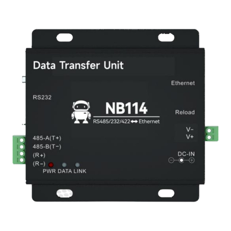
Ebyte ME31-XXAX0060 User manual

ME31-XXAX0060
Network I/O Networking Module
This manual may be updated with product improvements, please refer to the latest version of the
manual! Chengdu Yibaite Electronic Technology Co., Ltd. reserves the final interpretation and
modification rights for all contents in this instruction!

Chengdu Ebyte Electronic Technology Co.,Ltd. ME31-XXAX0060_UserManual_EN
Copyright ©2012–2023, Chengdu Ebyte Electronic Technology Co.,Ltd 1
Contents
I. Overview .......................................................................................................................................... 3
1.1 Product Introduction .........................................................................................................................................3
1.2 Functional Features .......................................................................................................................................... 3
1.3 Product Application Topology Diagram .......................................................................................................... 3
II.Quick use .................................................................................................................................................................... 5
2.1 Device preparation ........................................................................................................................................... 5
2.2 Device connection ............................................................................................................................................ 6
2.2.1 RS485 connection ................................................................................................................................. 6
2.2.2 Relay output connection ........................................................................................................................6
2.2.3 Simple use ............................................................................................................................................. 7
2.3 Parameter Configuration .................................................................................................................................. 7
2.4 Control Testing ................................................................................................................................................. 8
2.4.1 Modbus TCP control ............................................................................................................................. 8
2.4.2 Modbus RTU control .............................................................................................................................9
III. Technical Specification .......................................................................................................................................... 10
3.1 Specifications ................................................................................................................................................. 10
3.2 Device Default Parameters .............................................................................................................................10
3.3 Mechanical Dimensional Drawing .................................................................................................................11
3.4 Port and indicator light description ................................................................................................................12
IV. Product Function Introduction ................................................................................................................................14
4.1 DO output ....................................................................................................................................................... 14
4.1.1. Input count ..........................................................................................................................................14
4.1.2. Level output ........................................................................................................................................14
4.1.3. Pulse output ........................................................................................................................................ 14
4.1.4. Follow mode .......................................................................................................................................14
4.1.5. Reverse follow mode ..........................................................................................................................15
4.1.6. Trigger toggle mode ........................................................................................................................... 15
4.1.7. Power-on state .................................................................................................................................... 15
4.2 Modbus Gateway ............................................................................................................................................15
4.2.1. Modbus TCP/RTU protocol conversion ............................................................................................ 15
4.2.2. Modbus Address Filtering ..................................................................................................................15
4.2.3. Modbus TCP Protocol Data Frame Description ................................................................................ 16
4.2.4. Modbus RTU protocol data frame description .................................................................................. 16
4.3 Active upload ..................................................................................................................................................16
4.4 Custom Module Information ..........................................................................................................................17
4.4.1. Modbus Address .................................................................................................................................17
4.4.2. Module Name .....................................................................................................................................17
4.4.3. Network parameters ........................................................................................................................... 17
4.4.4. Serial Port Parameters ........................................................................................................................ 17
4.5 OLED display and parameter configuration .................................................................................................. 18
4.5.1. Information Display Interface ............................................................................................................18

Chengdu Ebyte Electronic Technology Co.,Ltd. ME31-XXAX0060_UserManual_EN
Copyright ©2012–2023, Chengdu Ebyte Electronic Technology Co.,Ltd 2
4.5.2. Equipment parameter display interface ............................................................................................. 18
4.5.3. Equipment Parameter Configuration Interface .................................................................................. 19
4.5.4. Screen Sleep ....................................................................................................................................... 19
4.6 MODBUS parameter configuration ............................................................................................................... 20
4.6.1. DO Register List .................................................................................................................................20
4.6.2. Module related registers .....................................................................................................................21
4.6.3. Network related registers ................................................................................................................... 21
4.6.4. Examples of Modbus command operation instructions .....................................................................22
V. Configuration Software ............................................................................................................................................25
5.1. Acquisition and Control ................................................................................................................................ 25
5.2. Parameter configuration interface .................................................................................................................26

Chengdu Ebyte Electronic Technology Co.,Ltd. ME31-XXAX0060_UserManual_EN
Copyright ©2012–2023, Chengdu Ebyte Electronic Technology Co.,Ltd 3
I. Overview
1.1 Product Introduction
ME31-XXAX0060 is equipped with 6-way A-type relay output, and
supports Modbus TCP protocol or Modbus RTU protocol for acquisition and
control. At the same time, the device is also a network I/O networking module
that can be used as a simple Modbus gateway (automatically send commands
with non-local Modbus addresses through the serial port/network port).
1.2 Functional Features
Support standard Modbus RTU protocol and Modbus TCP protocol;
Support various configuration software/PLC/touch screen;
RS485 acquisition control I/O;
RJ45 acquisition control I/O, support 4-way host access;
Support OLED display to display status information, and configure device parameters through buttons;
6-way switch output DO (A-type relay);
Switch output (DO) supports level mode, pulse mode, follow mode, reverse follow mode, trigger flip mode;
Support custom Modbus address setting;
Support 8 common baud rate configurations;
Support DHCP and static IP;
Support DNS function, domain name resolution;
Support Modbus gateway function;
1.3 Product Application Topology Diagram
Network interface application topology diagram

Chengdu Ebyte Electronic Technology Co.,Ltd. ME31-XXAX0060_UserManual_EN
Copyright ©2012–2023, Chengdu Ebyte Electronic Technology Co.,Ltd 4
Serial port application topology diagram

Chengdu Ebyte Electronic Technology Co.,Ltd. ME31-XXAX0060_UserManual_EN
Copyright ©2012–2023, Chengdu Ebyte Electronic Technology Co.,Ltd 5
II.Quick use
【Note】This test needs to be carried out with the default factory parameters.
2.1 Device preparation
The following table lists the items required for this test:
ME31-XXAX0060
12V switching power
supply
USB to RS485 Cable
A computer
A network cable
Several cables

Chengdu Ebyte Electronic Technology Co.,Ltd. ME31-XXAX0060_UserManual_EN
Copyright ©2012–2023, Chengdu Ebyte Electronic Technology Co.,Ltd 6
2.2 Device connection
2.2.1 RS485 connection
Note: When the 485 bus high-frequency signal is transmitted, the signal wavelength is shorter than the transmission
line, and the signal will form a reflected wave at the end of the transmission line, which will interfere with the original
signal. Therefore, it is necessary to add a terminal resistor at the end of the transmission line so that the signal does not
reflect after reaching the end of the transmission line. The terminal resistance should be the same as the impedance of the
communication cable, the typical value is 120 ohms. Its function is to match the bus impedance and improve the
anti-interference and reliability of data communication.
2.2.2 Relay output connection
External power supply
ME31 Device
User’s RS485 Device
Load

Chengdu Ebyte Electronic Technology Co.,Ltd. ME31-XXAX0060_UserManual_EN
Copyright ©2012–2023, Chengdu Ebyte Electronic Technology Co.,Ltd 7
2.2.3 Simple use
Wiring: The computer is connected to the RS485 interface of ME31-XXAX0060 through USB to RS485, A is
connected to A, and B is connected to B.
Networking: Insert the network cable into the RJ45 port and connect to the PC.
Power supply: Use DC-12V switching power supply (DC 8~28V) to power ME31-XXAX0060.
2.3 Parameter Configuration
Step 1: Modify the IP address of the computer to be consistent with the device. Here I am modifying it to
192.168.3.100 to ensure that it is on the same network segment as the device and that the IP is different. If you
cannot connect to the device after the above steps, please turn off the firewall and try again;
Step 2: Open the network assistant, select the TCP client, enter the remote host IP192.168.3.7 (default parameter),
enter the port number 502 (default parameter), and select HEX to send.
Network port

Chengdu Ebyte Electronic Technology Co.,Ltd. ME31-XXAX0060_UserManual_EN
Copyright ©2012–2023, Chengdu Ebyte Electronic Technology Co.,Ltd 8
2.4 Control Testing
2.4.1 Modbus TCP control
Use the network assistant to control the first DO output of ME31-XXAX0060.
Other functions can be tested through the commands in the table below.
The device is in server mode, and the
computer connects to the device as a client.
Enter the IP address of the device.
Enter the port number of the device.
Select HEX display to facilitate observation
of data.
Select HEX to send
1: Transaction ID
2: Protocol identifier
3: Length
4: Modbus address
5: Function code
6: First address
7: Opcode

Chengdu Ebyte Electronic Technology Co.,Ltd. ME31-XXAX0060_UserManual_EN
Copyright ©2012–2023, Chengdu Ebyte Electronic Technology Co.,Ltd 9
Function (function code)
Command
Pull in the first coil (0x05)
01 00 00 00 00 06 01 05 00 00 FF 00
Full open command (0x0F)
02 00 00 00 00 08 01 0F 00 00 00 06 01 3F
Full close command (0x0F)
02 00 00 00 00 08 01 0F 00 00 00 06 01 00
Read all DO status (0x01)
01 00 00 00 00 06 01 01 00 00 00 06
2.4.2 Modbus RTU control
Use the serial port assistant to control the first DO output of ME31-XXAX0060.
Other functions can be tested through the commands in the table below.
Function (function code)
Command
Pull in the first coil (0x05)
01 05 00 00 FF 00 8C 3A
Full open command (0x0F)
01 0F 00 00 00 06 01 3F DF 46
Full close command (0x0F)
01 0F 00 00 00 06 01 00 9F 56
Read all DO status (0x01)
01 01 00 00 00 06 BC 08
This manual suits for next models
5
Table of contents
Other Ebyte Modem manuals

Ebyte
Ebyte E840-DTU User manual

Ebyte
Ebyte E90-DTU User manual

Ebyte
Ebyte NB183 User manual

Ebyte
Ebyte ECAN-401S User manual

Ebyte
Ebyte E34-DTU User manual

Ebyte
Ebyte E62-DTU (433D30) User manual

Ebyte
Ebyte E90-DTU User manual

Ebyte
Ebyte E90-DTU User manual

Ebyte
Ebyte 230SL37 User manual

Ebyte
Ebyte 400SL22-GPRS User manual

Ebyte
Ebyte E880-IR01 User manual

Ebyte
Ebyte E800-DTU V8 Series User manual

Ebyte
Ebyte E90-DTU User manual

Ebyte
Ebyte MA02-AAC 2240 Series User manual

Ebyte
Ebyte ME31-XXXA0006 User manual

Ebyte
Ebyte EBT3001 User manual

Ebyte
Ebyte E92-DTU User manual

Ebyte
Ebyte E70-DTU User manual

Ebyte
Ebyte E95-DTU User manual

Ebyte
Ebyte E90-DTU User manual