Ebyte MA02-XACX0440 User manual

【4AI + 4DO】
MA02-XACX0440

Chengdu Ebyte Electronic Technology Co.,Ltd. 【4AI+4DO】MA02-XACX0440 User Manual
Copyright ©2012–2021,Chengdu Ebyte Electronic Technology Co.,Ltd. 1
Contents
Disclaimer............................................................................................................................................................. 4
1 Introduction........................................................................................................................................................5
1.1 Brief Introduction........................................................................................................................................5
1.2 Features....................................................................................................................................................... 5
2 Quick start.......................................................................................................................................................... 6
2.1 Preparation for use...................................................................................................................................... 6
2.2 Equipment wiring........................................................................................................................................6
2.2.1 Power wiring........................................................................................................................................ 6
2.2.2 Communication wiring RS232.............................................................................................................7
2.2.3 Overall wiring diagram........................................................................................................................ 7
2.3 Software settings......................................................................................................................................... 9
2.3.1 Device connection................................................................................................................................9
2.3.2 Equipment test....................................................................................................................................10
3 Product description...........................................................................................................................................11
3.1 Model Specification.................................................................................................................................. 11
3.2 Technical Parameter..................................................................................................................................11
3.3 Port Description........................................................................................................................................ 13
3.4 Dimensions................................................................................................................................................14
3.5 Installation method....................................................................................................................................14
4 Product Features...............................................................................................................................................15
4.1 Analog Input AI........................................................................................................................................ 15
4.1.1 Analog input AI description...............................................................................................................15
4.1.2 Analog input AI filter parameters...................................................................................................... 15
4.1.3 Analog input AI sampling range........................................................................................................15
4.1.4 Analog input AI raw value, engineering value.................................................................................. 16
4.1.5 Analog input AI calibration............................................................................................................... 16
4.2 Switch output DO......................................................................................................................................16
4.2.1 Switch output DO description............................................................................................................16
4.2.2 Switch output DO mode setting......................................................................................................... 17
4.3 Device address........................................................................................................................................ 17

Chengdu Ebyte Electronic Technology Co.,Ltd. 【4AI+4DO】MA02-XACX0440 User Manual
Copyright ©2012–2021,Chengdu Ebyte Electronic Technology Co.,Ltd. 2
4.3.1 Device address................................................................................................................................... 17
4.3.2 Hardware address (dip switch)...........................................................................................................18
4.3.3 Software address (offset address).......................................................................................................19
5 Port wiring........................................................................................................................................................20
5.1Analog input AI port wiring.......................................................................................................................20
5.1.1 Two-wire sensor wiring..................................................................................................................... 20
5.1.2 Three-wire sensor wiring................................................................................................................... 21
5.1.3 Four-wire sensor wiring..................................................................................................................... 21
5.2Switch output DO port wiring....................................................................................................................22
5.2.1 The output terminal directly controls the load (small power equipment within 1kW)......................22
5.2.2 Output terminal control contactor (contactor controls high-power....................................................22
220V equipment).........................................................................................................................................22
5.2.3 Output terminal control contactor (contactor controls high-power 380V equipment)...................... 23
6 Software use.....................................................................................................................................................24
6.1Software Installation.................................................................................................................................. 24
6.2Software function introduction.................................................................................................................. 25
6.2.1 IO demo interface...............................................................................................................................25
6.2.2Basic setting interface........................................................................................................................ 27
6.2.3Advanced settings interface............................................................................................................... 29
6.3Device status query.................................................................................................................................... 30
6.4Equipment status control............................................................................................................................31
7 Modbus use...................................................................................................................................................... 32
7.1 Register list........................................................................................................................................ 32
7.2AI related register list.................................................................................................................................34
7.3Instruction format (partial).........................................................................................................................35
7.3.1 Read DO output coil status................................................................................................................ 35
7.3.2 Read holding register......................................................................................................................... 35
7.3.3 Write a single holding register........................................................................................................... 35
7.3.4 Write multiple holding registers.........................................................................................................36
7.3.5 Write the status of a single DO coil................................................................................................... 36
7.3.6 Write multiple DO coil states.............................................................................................................37
7.3.7 Read input register............................................................................................................................. 37

Chengdu Ebyte Electronic Technology Co.,Ltd. 【4AI+4DO】MA02-XACX0440 User Manual
Copyright ©2012–2021,Chengdu Ebyte Electronic Technology Co.,Ltd. 3
Revision history.................................................................................................................................................. 38
About us.............................................................................................................................................................. 38

Chengdu Ebyte Electronic Technology Co.,Ltd. 【4AI+4DO】MA02-XACX0440 User Manual
Copyright ©2012–2021,Chengdu Ebyte Electronic Technology Co.,Ltd. 4
Disclaimer
EBYTE reserves all rights to this document and the information contained herein.
Products, names, logos and designs described herein may in whole or in part be
subject to intellectual property rights. Reproduction, use, modification or disclosure to
third parties of this document or any part thereof without the express permission of
EBYTE is strictly prohibited.
The information contained herein is provided “as is” and EBYTE assumes no
liability for the use of the information. No warranty, either express or implied, is given,
including but not limited, with respect to the accuracy, correctness, reliability and
fitness for a particular purpose of the information. This document may be revised by
EBYTE at any time. For most recent documents, visit www.ebyte.com.

Chengdu Ebyte Electronic Technology Co.,Ltd. 【4AI+4DO】MA02-XACX0440 User Manual
Copyright ©2012–2021,Chengdu Ebyte Electronic Technology Co.,Ltd. 5
1 Introduction
1.1 Brief Introduction
MA02-XACX0440 supports the acquisition of 4-channel sensor
analog input (AI), which is converted to serial port (RS232) and data is
transmitted to configuration software or PLC. The serial port I/O
networking module (also called "remote IO") that realizes the remote
acquisition and control function by issuing commands through the serial
port to control 4 relay switch outputs (DO).
1.2 Features
★Support Modbus RTU protocol;
★Support various configuration software/PLC/touch screen;
★RS232 acquisition and control IO;
★DC 8~28V power supply;
★4 analog inputs AI (0~20mA/4~20mA);
★4 switch output DO (relay);
★Switch output (DO) supports level mode and pulse mode;
★Input collection port isolation protection;
★Communication baud rate 1200~115200 (default 9600), support custom setting;
★Supports 1~247 slave stations, 5-digit DIP switch can set 1~31 address code, more than 31 can
be set by software.
Chengdu Ebyte Electronic Technology Co.,Ltd. 【4AI+4DO】MA02-XACX0440 User Manual
Copyright ©2012–2021,Chengdu Ebyte Electronic Technology Co.,Ltd. 6
2 Quick start
If there is a problem during use, click on the official website link:
https://www.ebyte.com/product-class.aspx
2.1 Preparation for use
Before using the serial port I/O networking device (hereinafter referred to as "IO device"), you need
to prepare a computer, converter, power supply, screwdriver and other related auxiliary materials.
details as follows:
Table 2-1-1 Preparation list
Serial
Number
Device
Quantity
1
IO device
1
2
USB to serial converter
1
3
Configuration tool software
1
4
Computer
1
5
Power adapter (12V/1A)
1
6
Screwdriver (Slot SL 2)
1
7
Signal generator (or sensor)
1
2.2 Equipment wiring
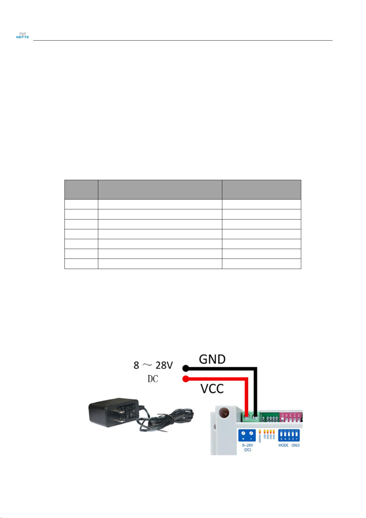
2.2.1 Power wiring
Power supply, using DC 8-28V power supply, can also use DC 12V or 24V power supply.
Figure 2-2-1 Power wiring diagram
Chengdu Ebyte Electronic Technology Co.,Ltd. 【4AI+4DO】MA02-XACX0440 User Manual
Copyright ©2012–2021,Chengdu Ebyte Electronic Technology Co.,Ltd. 7
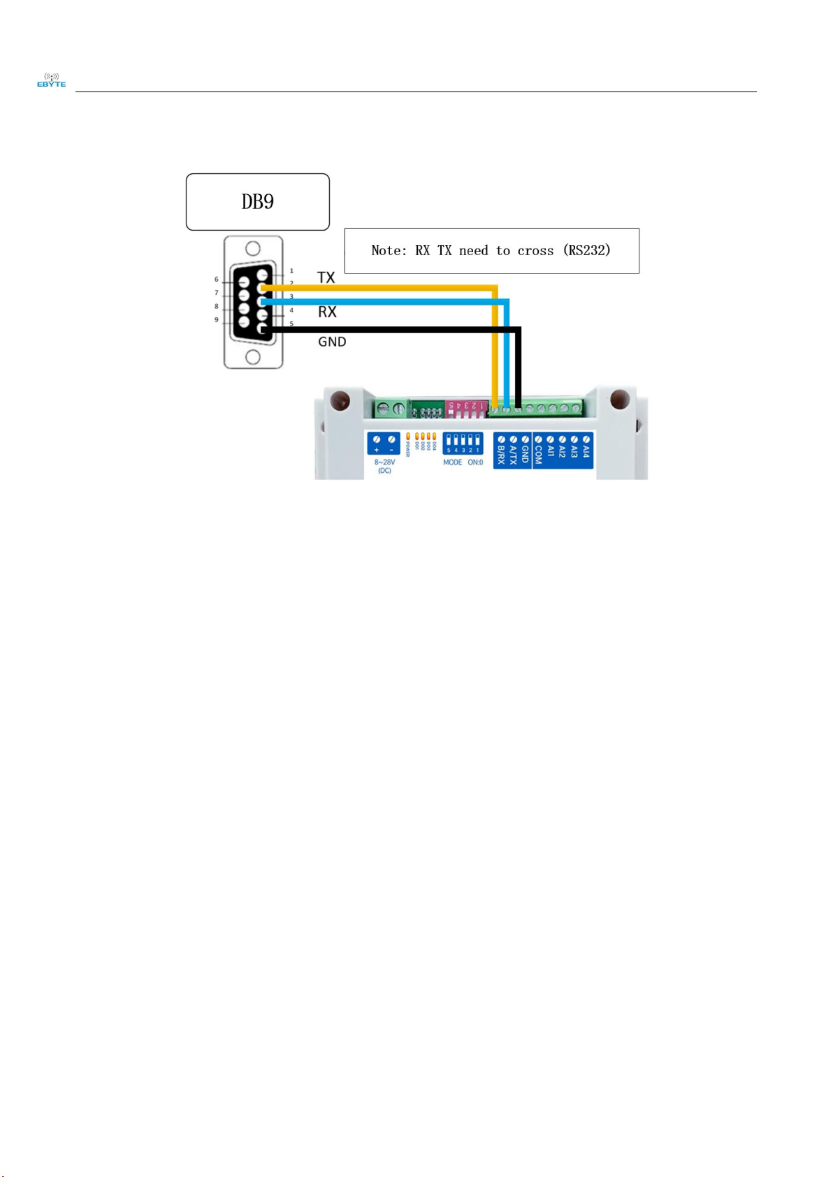
2.2.2 Communication wiring RS232
Figure 2-2-2 Communication RS232 wiring diagram
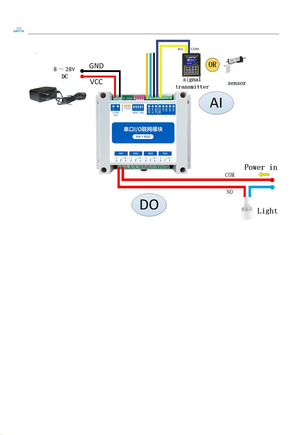
2.2.3 Overall wiring diagram
(1) After the equipment is powered on, the power indicator (POWER) is always on, and the
equipment power supply is normal.
(2) Analog input AI wiring, connect the signal generator to the analog input AI port as shown in the
figure.
(3) Switch output DO wiring, connect the load to the switch output DO port as shown in the figure.
Chengdu Ebyte Electronic Technology Co.,Ltd. 【4AI+4DO】MA02-XACX0440 User Manual
Copyright ©2012–2021,Chengdu Ebyte Electronic Technology Co.,Ltd. 8
Figure 2-2-2 Overall wiring diagram

Chengdu Ebyte Electronic Technology Co.,Ltd. 【4AI+4DO】MA02-XACX0440 User Manual
Copyright ©2012–2021,Chengdu Ebyte Electronic Technology Co.,Ltd. 9
2.3 Software settings
2.3.1 Device connection
Figure 2-3-1 Software interface
Steps:
(1) Open the serial port, find the corresponding device port number, the baud rate defaults to
9600, and click ‘open serial port’.
Figure 2-3-2 Open the serial port
(2) In the device window, click ‘Search Device’, and the log window on the right will start to
refresh the search information. After the connected device is displayed in the device column
of the device window, click the "Stop Searching" menu. Then select the device and click, the
connection is successful.
Table of contents
Other Ebyte Modem manuals

Ebyte
Ebyte MA02-XXCX0080 User manual

Ebyte
Ebyte E831-RTU Series User manual

Ebyte
Ebyte E32-DTU User manual

Ebyte
Ebyte E851-RTU User manual

Ebyte
Ebyte E90-DTU User manual

Ebyte
Ebyte E32-DTU User manual
-V8 User manual")
Ebyte
Ebyte E32-DTU(900L300)-V8 User manual

Ebyte
Ebyte E90-DTU-V8 User manual

Ebyte
Ebyte E34-DTU User manual

Ebyte
Ebyte ECAN-E01 User manual

Ebyte
Ebyte E95-DTU User manual

Ebyte
Ebyte E90-DTU User manual

Ebyte
Ebyte ECAN-U01 User manual

Ebyte
Ebyte E34-DTU User manual

Ebyte
Ebyte E810-DTU User manual

Ebyte
Ebyte E90-DTU User manual

Ebyte
Ebyte E90-DTU User manual

Ebyte
Ebyte E180-DTU User manual

Ebyte
Ebyte E96-DTU User manual

Ebyte
Ebyte 400SL22-GPRS User manual


