Data I/O PSV7000 User manual
Machine Components
pages 1, 2, 3
Run a Job
page 15
Chart for ‘My Jobs’
page 70
Collecting Log Files
page 77
096-0461-001G
with
programmers
OPERATOR’SMANUAL
Automated Programming and Handling
OPERATOR’SMANUAL

096-0461-001G March 2018
Data I/O has endeavored to ensure that the information in this document is accurate and
complete. Data I/O assumes no liability for errors, or for any incidental, consequential, indirect,
or special damages, including, without limitation, loss of use, loss or alteration of data, delays,
or lost profits or savings, arising from the use of this document or the product which it
accompanies.
No part of this document may be reproduced or transmitted in any form or by any means,
electronic or mechanical, for any purpose, without written permission from Data I/O
Corporation.
Data I/O, TaskLink, PSV7000, FlashCORE and Lumen[X] are trademarks of Data I/O
Corporation.
Data I/O Corporation acknowledges the trademarks of other organizations for their respective
products or services mentioned in this document.
© 2014–2018 Data I/O Corporation
All rights reserved

Data I/O • PSV7000 Operator’s Manual i
1Contents
P S V 7 0 0 0 O p e r a t o r ’ s M a n u a l
PSV7000 Machine Components 1
Work Surface Components 2
Power Panel Components 3
Programmer Overview 4
LumenX 4
FlashCORE 5
Supported Integrated Circuits (Devices) 6
Operation • 7
Safety Messages and Precautions 8
Warnings and Cautions 8
Safety Symbols 9
Safety Systems 10
Emergency Stop (E-Stop) Buttons 10
Safety Doors and Interlocks 11
Electrostatic Discharge 12
General Precautions 14
Running a Job on PSV7000 15
Requirements 15
List of Steps to Start a Job 15
1» Checking the System 17
2» Installing Input/Output Media 18
Setting Up Static Trays 18
Vibration Tube Input Option—Loading 21
Installing the Tape Feeder Module Option 22
Installing the Tape Take-up Module Option 25
Checking the Tape Output Option 25
3» (Optional) Performing 3D Coplanarity Inspection 27
4» (Optional) Set up Other Equipment 29
5» Socket Adapters and Actuator Plates 30
Finding Socket Adapter Part Numbers 30
(FC) Installing Adapters and Actuators 32
(FC) Adjusting the Actuator Plates 34
(LumenX) Installing Adapters and Actuators 35
(LumenX) Adjusting the Actuator Plates 37
6» Installing the Correct Probes 38
Removing and Installing a Probe 40

Contents
ii Data I/O • 096-0461-001G
7» If Laser Marking—Installing the Correct Rotor Tips 46
8» Turning PSV7000 System Power ON 48
9» Selecting a Job—Starting AH700 Indirectly 49
Using TaskLink (FlashCORE programmers) 49
Using LumenX Data Management Software (DMS) 51
10» (Optional) Preselecting Programmers 53
11» Setting Media and Options—the Setup Window 54
Verifying Media Setup 55
Aligning the Tape-Input Pick Point 57
Loading the Tape-In Take Up Reel (Option) 57
12» Starting Programming 58
If Laser Marking—Starting the Laser PC 58
(Optional) View of Laser Status 59
Starting the Fume Extractor (if not already) 60
Programming Errors 61
Run Window Socket Color Meanings 61
What do the Numbers Mean? 61
Programming Results Interpreted at the Socket 62
Removing Devices 63
Stopping the System 63
Emergency Stop 64
Pausing a Job 65
Ending a Job 66
Light Tower Interpretation 67
Changing Programmer Status 68
Disabling Programmers 68
Clearing a Disabled Status 68
My Jobs that Use the Same Setup 70
Finishing a Job 72
Turning PSV7000 System Power OFF 72
Dual Tray Feeder 74
Operating the Dual Tray Feeder ‘EX’ 74
Additional Features 76
Automotive Performance Pak 76
If You Have Trouble 77
Collecting System Logs 77
Programmer Related Problems 77
My Notes 78
Index • 79
■ PSV7000 Machine Components ◘
PSV7000 Operator’s Manual —1—
back
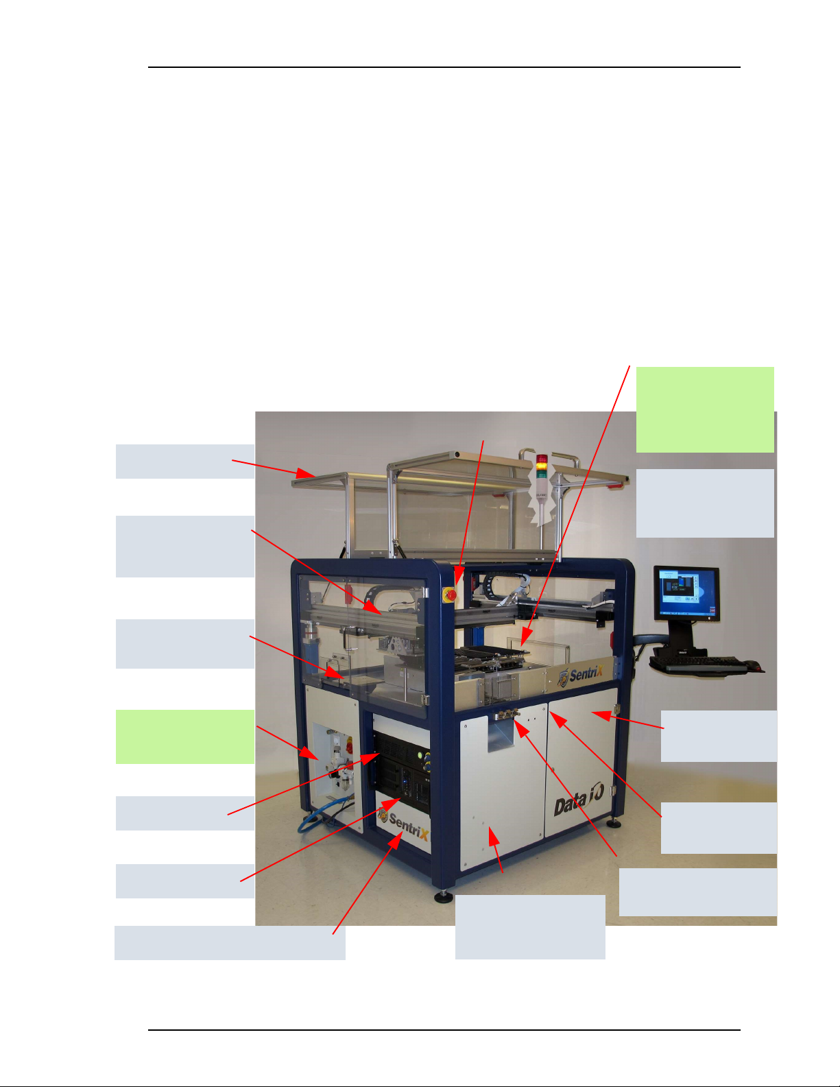
PSV7000 Machine Components
This Visual Index of PSV7000 features and subassemblies locates them on the machine
and in this manual.
Figure 1: The Big Picture—features of PSV7000.
Power Panel —see the
figure on page 3. ð
Support for Tape Feeder
and Vibratory Tube Media
Support and connec-
tion for Tray Feeder,
far side, not shown.
ESD connection;
page 2
Laser computer
1. E-Stops • page 10
2. Light Tower • page 67
3. Gantry & PNP head • see
Owner’s Manual
4. PNP head probes • page 38
5. Workspace
6. Tape Output • page 25
7. Tape Input • page 22;
Vibratory Tube Media •
page 21
8. Anti-static ground strap
connections • page 2
9. Monitor, keyboard, mouse
10. Handler Computer
11. Laser Computer • page 58
12. Programmers • page 2
13. Power Panel • page 3 and
Owner’s Manual for more
14. Safety doors
15. Access doors (front, two rear)
16. Take-Up spool for Tape-Input
• Contact Sales
17. 3D Coplanarity Inspection Sys-
tem computer
Gantry (supports PNP
head which is hidden
in this view)
The Work surface:
Input and Output
options. See the figure
on page 2.
Handler computer
2
1
5, 12
3, 4
13
11
10
7
8
9
Tape Output Module
mount
6
Safety doors
14
Access doors, one
front, two rear
15
Optional Tape Take-up
Module (not shown)
page 25
16
17
3D Coplanarity computer (not shown)

■ PSV7000 Machine Components
—2— Data I/O • 096-0461-001G
back
Work Surface Components
Figure 2: Some features on the PSV7000 work surface—
shown here with static trays and 11 programmers.
1The system can be configured with a reject tray or a reject bin or both
except when 3D Inspection Model UX is installed. Note that the static
trays and Dual Tray Feeder would not both be used. (Refer to Owner’s
Manual or on-screen Help).
ïThe Big Picture
Tray-capture
magnet (3)
The Power Panel ð
Laser Rotor (rotates)
Laser Module
Antistatic connection
Reject Bin1
Reject Tray1
Tape-In Module
(Tape Feeder)
FlashCORE Programmers
(11 shown)
LumenX Programmers (4
shown) with some Flash-
CORE. See page 4.
Input & Output Trays
Tray alignment pins
Antistatic connections
Tape-Output
Module
3D-Lead Inspec-
tion System.
Model VX shown.
This label color = Optional equipment
Laser Rotor tips (2)
Dual Tray Feeder EX
■ PSV7000 Machine Components ◘ Power Panel Components
PSV7000 Operator’s Manual —3—
back
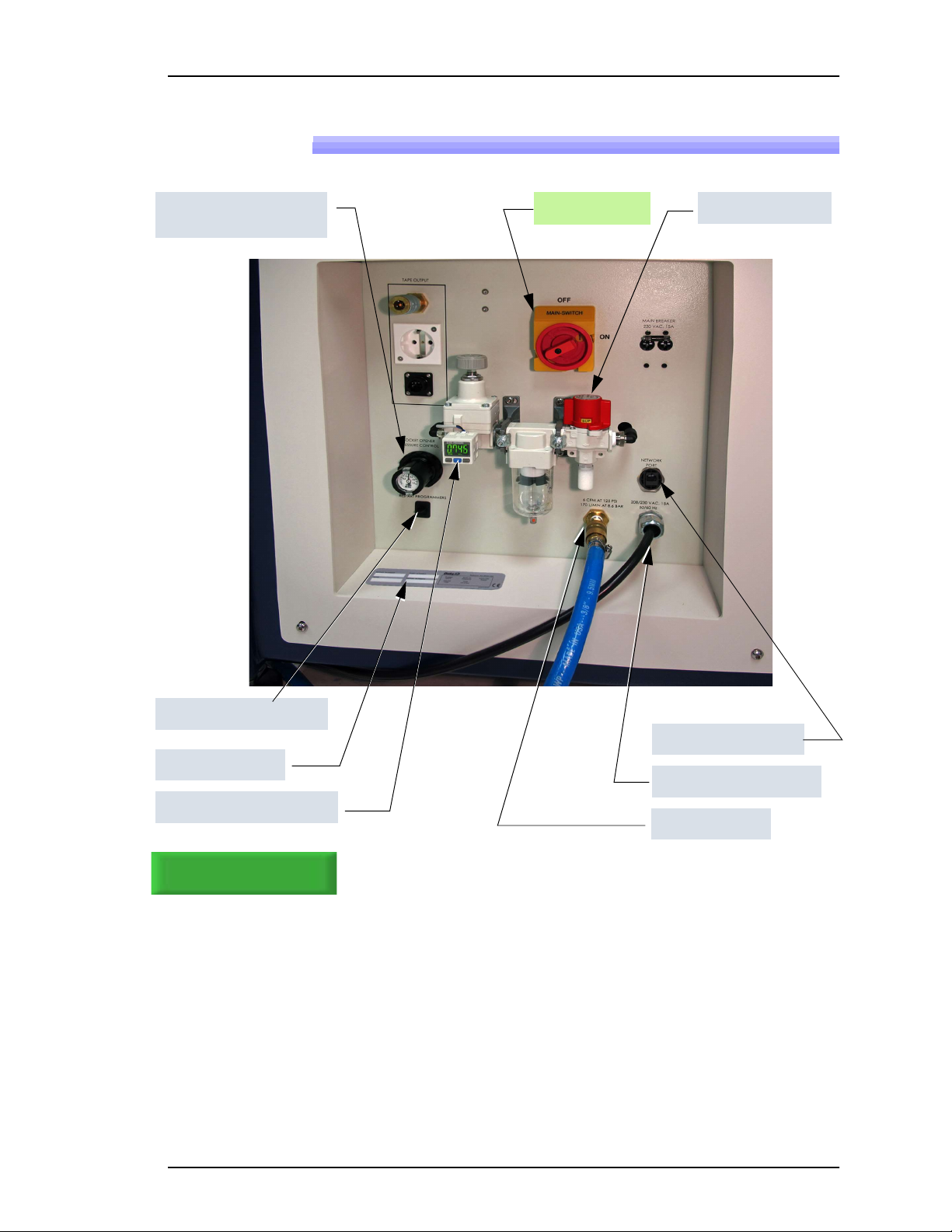
Power Panel Components
Figure 3: Rear View of PSV7000. For information on connecting the
facilities, see the Owner’s Manual.
Power Switch Main air valve
ïThe Big Picture, page 1
Main air inlet
AC power connection
Network connection
Serial Number
Main Pressure Regulator
Programmer Power only
Socket Opener Pressure
Regulator

■ PSV7000 Machine Components
—4— Data I/O • 096-0461-001G
back
Programmer Overview
LumenX
LumenX is Data I/O’s latest programmer at the time of this document.
Each LumenX programmer requires one to two Actuator Plates and
one to eight Socket Adapters for the specific device package being
programmed. Each Socket Adapter has one socket.
Figure 4: One LumenX programmer with eight Sockets.
LED Interpretation on LumenX Programmers
Figure 5: Each LumenX Socket Adapter has four LEDs and indicates
PIN 1 as shown. All four LEDs light at once only during startup and go
off when the startup procedure is complete. The Actuator Plate is not
shown here for clarity.
Green = PASS PROGRAMMING
Yellow = BUSY
Red = FAILED PROGRAMMING
White = CONTINUITY ERROR
Jobs for LumenX pro-
grammers are created
with LumenX Data Man-
agement Software.
Actuator Plates
Socket Adapters
(small arrows)
Clamp (4)
Spring Clip (4)
Programmer

■ PSV7000 Machine Components ◘ Programmer Overview
PSV7000 Operator’s Manual —5—
back
FlashCORE
FlashCORE III is a robust programming engine supplied in the
PS-Family of products. Each programmer requires an Actuator Plate
and a Socket Adapter for the specific device package being pro-
grammed. Socket Adapter can have up to four sockets on them.
Figure 6: FlashCORE III programmers.
LED Interpretation on FlashCORE Programmers
Figure 7: Each FlashCORE Socket Adapter has one red LED per socket.
A) Standard Adapter; socket 2 has failed. B) HIC Adapter. Socket 3 has
failed. The Actuator Plate is not shown on the HIC Adapter for clarity.
Steady Red = FAILED PROGRAMMING
Jobs for FC program-
mers are created with
TaskLink Software.
One Actuator Plate
each
Socket Adapter
clamp
One Socket
Adapter each
A
B

■ PSV7000 Machine Components
—6— Data I/O • 096-0461-001G
back
Supported Integrated Circuits (Devices)
• Flash Memory:
NOR, NAND, MCP, MMC, e.MMC, SD, MoviNAND,
OneNAND, iNAND, Serial Flash, EEPROM, EPROM
• Microcontrollers
• Logic devices:
CPLDs, FPGAs, PLDs
For all available
devices supported,
see the Data I/O
website and click
Device Search
.
Other manuals for PSV7000
1
Table of contents
Other Data I/O Motherboard manuals


