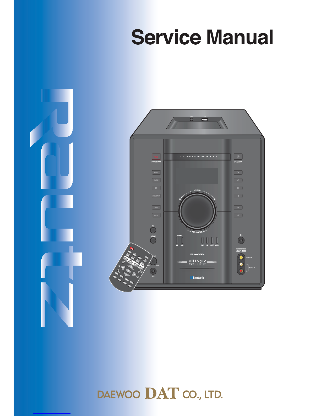
Daewoo Rautz NC-8008EB User manual

MiniComponentSoundSystem
SN: 9CD8308400
Apr. 2010
Model : NC-8008EB/NC-8009EB TI
( )

Table of Contents
Mini Component Sound System
Model : NC-8008EB
NC-8009EB
Safety Precautions ........................................................... 1
Specifications ................................................................... 2
Trouble Shooting Guide .................................................. 3
Exploded View and Mechanical Parts List ........................ 4
Wiring Diagram ................................................................ 5
Block Diagram .................................................................. 6
Schematic Diagram .......................................................... 7
●
Front Section
●
SMPS Section
●
CD Section
●
MAIN Section
P.C.B Pattern Layout ........................................................ 8
●
Front
●
CD
●
MAIN
●
Jack/Key
●
SMPS
Appendix - Electrical Key part list.
....................................... 9

Safety Precautions
1
2
3
4
5
6
7
8
9
10
11
12
13
14
15
1
2
3
4
5
6
7
8
9
10
11
12
13
14
15
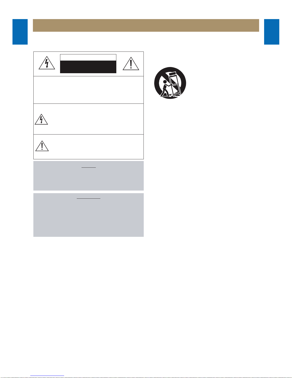
WARNING
: TO PREVENT FIRE OR ELECTRIC SHOCK, DO NOT EXPOSE
THIS APPLIANCE TO RAIN OR MOISTURE.
CAUTION :
TO REDUCE THE RISK OF ELECTRIC SHOCK, DO NOT
REMOVE COVER (OR BACK). NO USER SERVICEABLE PARTS
INSIDE.
REFER SERVICING TO QUALIFIED SERVICE PERSONNEL.
THIS SYMBOL IS INTENDED TO ALERT THE USER TO THE
PRESENCE OF UNINSULTED "DANGEROUS VOLTAGE"
WITHIN THE PRODUCT'S ENCLOSURE THAT MAY BE
SUFFICIENT MAGNITUDE TO CONSTITUTE A RISK OF
ELECTRIC SHOCK TO PERSONS.
THIS SYMBOL IS INTENDED TO ALERT THE USER TO THE
PRESENCE OF IMPORTANT OPERATING AND MAINTENANCE
(SERVICING) INSTRUCTIONS IN THE LITERATURE
ACCOMPANYING THE APPLIANCE.
CAUTION
TO PREVENT ELECTRIC SHOCK, DO NOT USE THIS POLARIZED AC
PLUG WITH AN EXTENSION CORD, RECEPTACLE OR OTHER OUTLET
UNLESS THE BLADES CAN BE FULLY INSERTED TO PREVENT BLADE
EXPOSURE.
LASER SAFETY
THIS UNIT EMPLOYS A LASER. ONLY QUALIFIED SERVICE PERSONNEL
SHOULD REMOVE THE COVER OR ATTEMPT TO SERVICE THIS DEVICE
DUE TO POSSIBLE EYE INJURY.
CAUTION :
USE OF ANY CONTROLS, ADJUSTMENTS, OR PROCEDURES
OTHER THAN THOSE SPECIFIED HEREIN MAY RESULT IN HAZARDOUS
RADIATION EXPOSURE.
CAUTION :
TO PREVENT ELECTRIC SHOCK, MATCH WIDE BLADE OF
PLUG TO WIDE SLOT, FULLY INSERT.
ATTENTION :
POUR EVITER LES CHOCS ELECTRIQUES, INTRODUIRE
LA LAME LA PLUS LARGE DE LA FICHE DANS LA BORNE CORRESPON-
DANTE DE LA PRISE ET POUSSER JUSQU'AU FOND.
Important Safety Instructions
- All the safety and operating instructions should be read before
the appliance is operated.
- The safety and operating instructions should be retained for
future reference.
- All warnings on the appliance and in the operating instructions
should be adhered to.
- All operating and use instructions should be followed.
1. Water and Moisture - The appliance should not be used near
water - for example, near a bathtub, washbowl, kitchen sink,
laundry tub, in a wet basement, or near a swimming pool,
and the like.
2. Carts and Stands - The appliance
should be used only with a cart or
stand that is recommended by th
manufacturer.
3. An appliance and cart combination
should be moved with care. Quick
stops, excessive force, and uneven
surfaces may cause the appliance
and cart combination to overturn.
4. Wall or Ceiling Mounting - The appli-
ance should be mounted to a wall or
ceiling only as recommended by the manufacturer.
5. Ventilation - The appliance should be situated so that its
location or position does not interfere with its proper
ventilation. For example, the appliance should not be situated
on a bed, sofa, rug, or similar surface that may block the
ventilation openings; or, placed in a built-in installation, such
as a bookcase or cabinet that may impede the flow of air
through the ventilation openings.
6. Heat - The appliance should be situated away from heat
sources such as radiators, heat registers, stoves, or other
appliances (including amplifiers) that produce heat.
7. Power Sources - The appliance should be connected to a
power supply only of the type described in the operating
instructions or as marked on the appliance.
8. Grounding or Polarization - The precautions that should be
taken so that the grounding or polarization means of an
appliance is not defeated.
9. Power - Cord Protection - Power-supply cords should be
routed so that they are not likely to be walked on or pinched
by items placed upon or against them, paying particular
attention to cords at plugs, convenience receptacles, and the
point where they exit from the appliance.
10.Protective Attachment Plug - If the appliance is equipped with
an attachment plug having overload protection. This is a
safety feature. See Instruction Manual for replacement or
resetting of protective device. If replacement of the plug is
required, be sure the service technician has used a
replacement plug specified by the manufacturer that has the
same overload protection as the original plug.
11.Cleaning - The appliance should be cleaned only as
recommended by the manufacturer.
12.Power Lines - An outdoor antenna should be located away
from power lines.
CAUTION
RISK OF ELECTRIC SHOCKS
DO NOT OPEN
PORTABLE CART
Figure 2

Safety Precautions
1
2
3
4
5
6
7
8
9
10
11
12
13
14
15
1
2
3
4
5
6
7
8
9
10
11
12
13
14
15
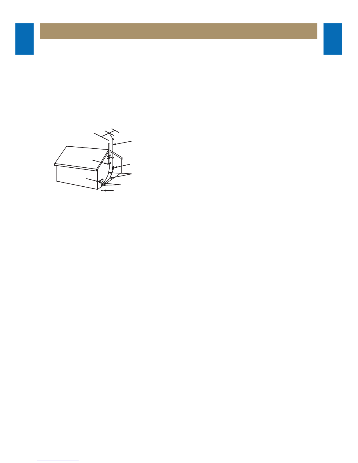
13.Outdoor Antenna Grounding - If an outside antenna is
connected to the receiver be sure the antenna system is
grounded so as to provide some protection against voltage
surges and built-up static charges. Article 810 of the National
Electrical Code, ANSI/NFPA 70, provides information with
regard to proper grounding of the mast and supporting
structure, grounding of the lead-in wire to an antenna-dis
charge unit, size of grounding conductors,location of antenna-
discharge unit, connection to grounding electrodes and
requirements for the grounding electrode. See Figure 1.
14.Non-use Periods - The power cord of the appliance should be
unplugged from the outlet when left unused for a long period
of time.
15.Object and Liquid Entry - Care should be taken so that objects
do not fall and liquids are not spilled into the enclosure through
openings.
16.Damage Requiring Service - The appliance should be
serviced by qualified service personnel when:
a) The power-supply cord or the plug has been damaged; or
b) Objects have fallen, or liquid has been spilled into the
appliance; or
c) The appliance has been exposed to rain; or
d) The appliance does not appear to operate normally or
exhibits a marked change in performance; or
e) The appliance has been dropped, or the enclosure
damaged.
17.Servicing - The user should not attempt to service the
appliance beyond that described in the operating instructions.
All other servicing should be referred to qualified service
personnel.
ANTENNA DISCHARGE UNIT
(NEC SECTION 810-20)
ANTENNA LEAD
IN WIRE
POWER SERVICE GROUNDING
ELECTRODE SYSTEM
(NEC ART 250 PART H)
GROUND CLAMP
ELECTRIC
SERVICE
EQUIPMENT
GROUNDING CONDUCTORS
(NEC SECTION 810-21)
GROUND CLAMPS
EXAMPLE OF ANTENNA
GROUNDING
NEC - NATIONAL ELECTRICAL CODE

Specifications
1
2
3
4
5
6
7
8
9
10
11
12
13
14
15
1
2
3
4
5
6
7
8
9
10
11
12
13
14
15
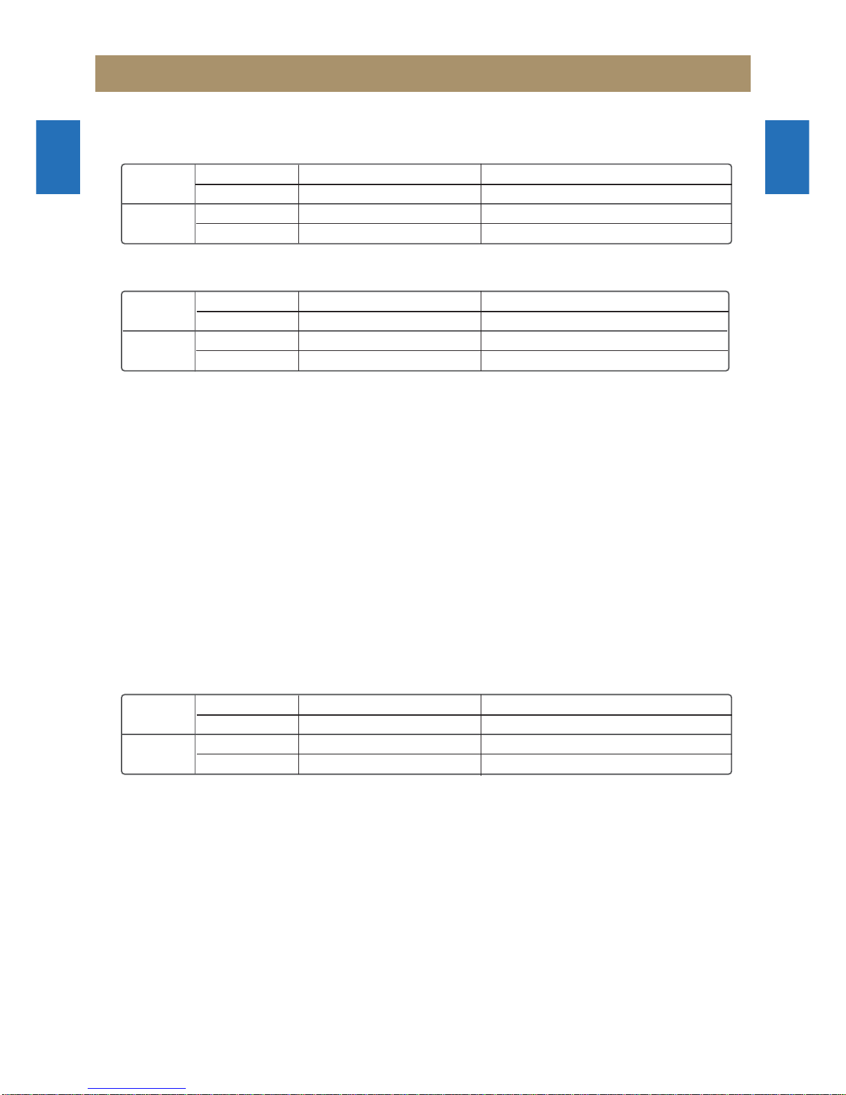
Dimensions (W x D x H / mm)
Model
Dimensions
Model
Dimensions
Set
Speaker
NC-8008EB
275 x 306 x 317.5 mm
AS-8009ZF
224 x 266.5 x 346 mm
NC-8009EB
275 x 306 x 317.5 mm
AS-8009ZF / AS-8009SW
224 x 266.5 x 346 mm / 245.5 x 330 x 317.5 mm
Weight (Set + Speaker / Kg)
Power supply
Voltage AC 100 V ~ 240 V (50/60 Hz)
Power consumption (Operating)
NC-8008EB : 90 Watt NC-8009EB : 110 Watt
Power save mode of Stand-by : Less than 1 Watt
Reception range
FM : 87.5 MHz ~ 108 MHz AM(MW) : 520 ~ 1,710 kHz (522 ~ 1,620 kHz)
Compact Disc player
Converter : 24 bit A/D, 24 bit D/A
Amplifier/Speakers
Due to the constant improvement of our products these specifications are subject to change without notice.
Model
Weight
Model
Weight
Set
Speaker
NC-8008EB
4.6 Kg
AS-8009ZF
5.5 Kg x 2 EA
NC-8009EB
4.7 Kg
AS-8009ZF / AS-8009SW
5.5 Kg x 2 EA / 7.5 Kg
Model
Total Power
Model
Impedance
Amplifier
Speaker
(3 Way)
NC-8008EB
200 W x 2
AS-8009ZF
4Ω
NC-8009EB
250 W x 2 / SW : 250 W
AS-8009ZF / AS-8009SW
FRONT : 4 Ω/ SW : 4 Ω

1
2
3
4
5
6
7
8
9
10
11
12
13
14
15
1
2
3
4
5
6
7
8
9
10
11
12
13
14
15
Trouble Shooting Guide
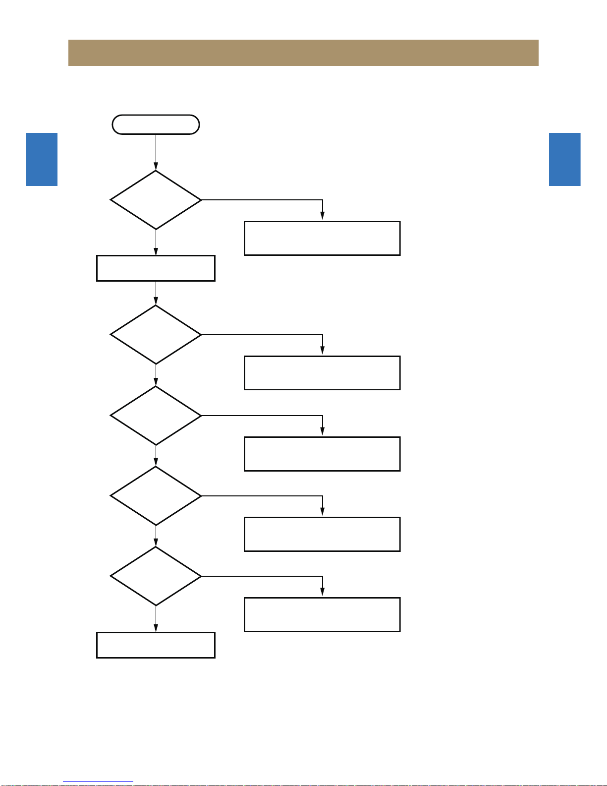
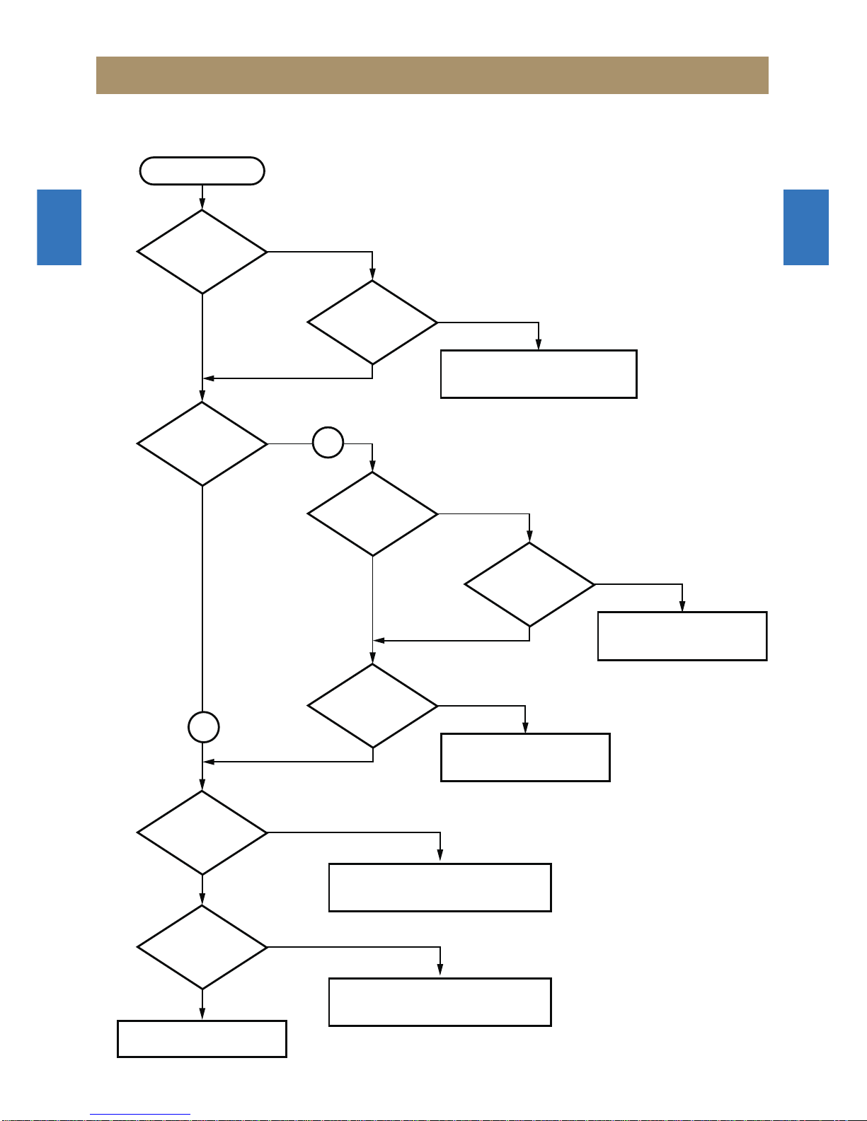
START
Basic Operation
OK
Standby LED
on?
Power on?
Initial read work?
Play?
Output Audio?
Turn Power on
Check Power Supply Circuit
Check Connection CW705 and CW 707
Check IC501 (MLC3895).
Check Standby Section in the SMPS
Check CD Mechanism
Check Power Supply Section
Check CD Region
Check CD Circuit IC501
Check Audio Section
No
Yes
No
Yes
No
Yes
No
Yes
No
Yes

1
2
3
4
5
6
7
8
9
10
11
12
13
14
15
1
2
3
4
5
6
7
8
9
10
11
12
13
14
15
Trouble Shooting Guide
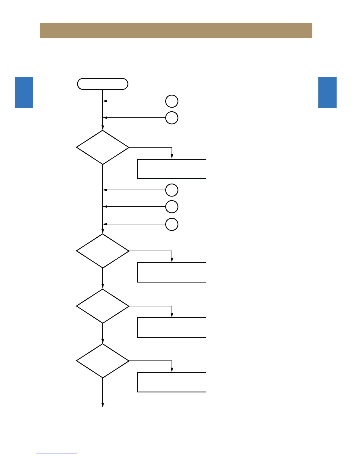
START
Initial Operation
Initial Operation OK
Standby LED
ON?
Power on?
Display Clock on the
VFD?
VFD Driver Interface
is OK?
Check Connection CW707
Check Power Supply
Check data line between IC501 and 701
Replace Flash Memory and SDRAM
Check VFD Data Interface (VFD_DATA/CLK)
Replace Front PCB Ass'y
No
Yes
Yes
Supply ST_3.3V? No
PWR_ON(19p) of
IC501 is HIGH?
Replace XC701
No
Yes
Yes
OSC waveform of
XC501 is OK?
No
Replace IC501
Yes
P_SAVE of IC501
(89p) is HIGH?
No
No
Yes
No
Yes
No
Yes
1
2

1
2
3
4
5
6
7
8
9
10
11
12
13
14
15
1
2
3
4
5
6
7
8
9
10
11
12
13
14
15
Trouble Shooting Guide
Start
USB Function
BLUETOOTH Function
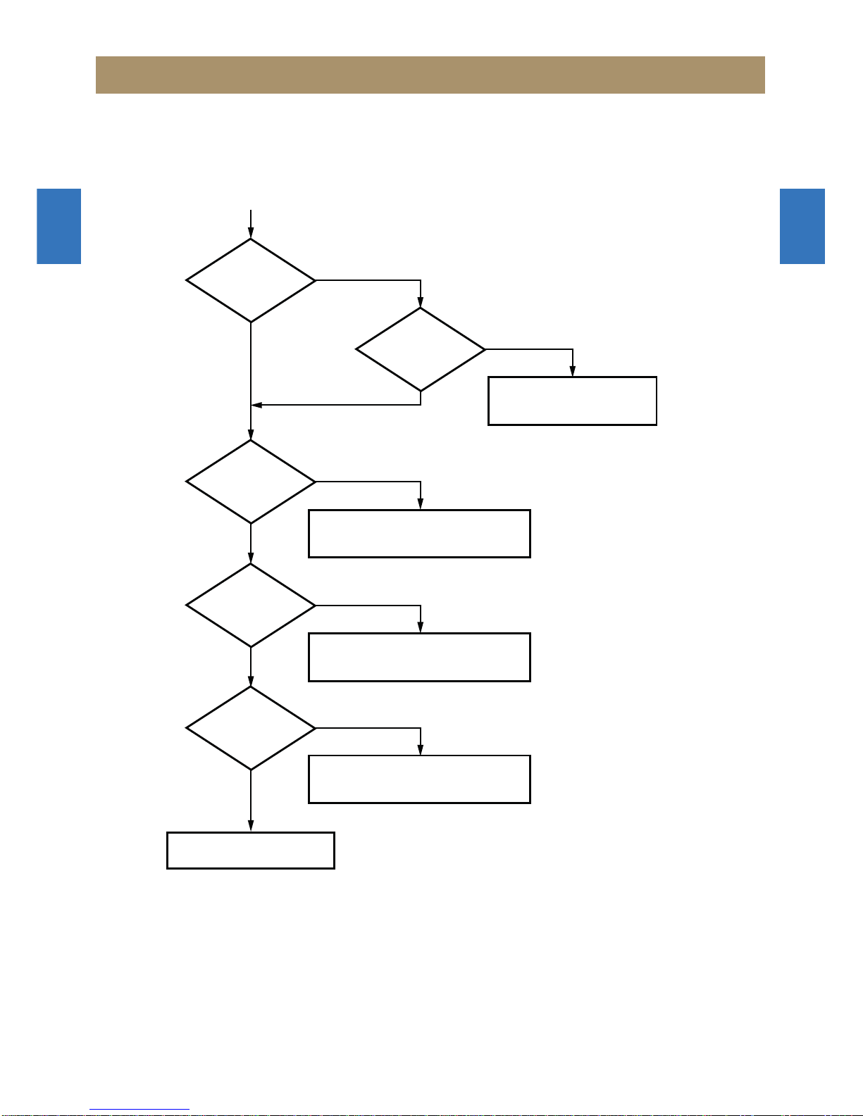
3-1. Audio(CD) Abnormal
Analog Output of
IC507 is OK?
Analog Input of
IC401 is OK?
No
Yes
Check the Connection CW505
Replace IC507
No
Yes
Analog Input of
IC801 is OK?
Check Pre-AMP Output (IC402)
No
Yes
U2S Input of
IC801 is OK?
Check I2S Output of IC802
No
Yes
1
2
AUX Function
GAME Function
3
4
TUNER Function
5
Audio Abnormal of CD Function

1
2
3
4
5
6
7
8
9
10
11
12
13
14
15
1
2
3
4
5
6
7
8
9
10
11
12
13
14
15
TroubleShootingGuide
OK
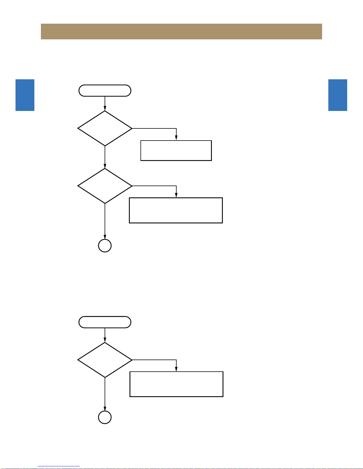
Check Bias Voltage 3,3V of IC803/804
Check short between Signal to GND or VCC
Check LPF L801 to L806
Check Supplied Power 3.3V
Yes
Supplied Power
is OK? No
PWM Output of
IC801 is OK?
PWM Output of
DigitalAMP is OK?
No
Yes
No
Yes
CheckAMP-PD(37p) of IC801
No
Yes
No
Yes
Power Down of
DigitalAMP is OK?
Speaker Output
is OK?

1
2
3
4
5
6
7
8
9
10
11
12
13
14
15
1
2
3
4
5
6
7
8
9
10
11
12
13
14
15
Trouble Shooting Guide
Start
3-2. Audio(USB) Abnormal
Data of
CW506 is OK?
No
Yes Check USB PCB
Replace J703
USB Input of
IC501 is OK?
No
Yes
1
Audio Abnormal of Digital(USB) Input Function
Check IC501 USB Data Input
Check Pin 120(D+)/131(D-) of IC501
ReplaceIC501
Start
3-3. Audio(BLUETOOTH) Abnormal
Bluetooth Input of
IC501 is OK?
No
Yes
2
Audio Abnormal of Digital(Bluetooth) Input Function
Check IC501 Bluetooth Data Input
Check Pin 75~78/117 of IC501
ReplaceIC511
This manual suits for next models
1
Table of contents
Other Daewoo Stereo System manuals

Daewoo
Daewoo XL-115 User manual

Daewoo
Daewoo AMI-917L User manual

Daewoo
Daewoo MC-5911SC User manual

Daewoo
Daewoo AMI-921DP User manual

Daewoo
Daewoo XG-318 User manual

Daewoo
Daewoo RG-361 User manual

Daewoo
Daewoo AMI-208MC User manual

Daewoo
Daewoo AMI-V225M User manual

Daewoo
Daewoo DV - 115 User manual

Daewoo
Daewoo AXW-217 User manual

Daewoo
Daewoo AMI-917L User manual

Daewoo
Daewoo AXL-125 User manual

Daewoo
Daewoo AMI-316L User manual

Daewoo
Daewoo AMI-717L User manual

Daewoo
Daewoo AMI-230 User manual

Daewoo
Daewoo AMI-716L User manual

Daewoo
Daewoo AMI-310 User manual

Daewoo
Daewoo RL-411 User manual

Daewoo
Daewoo XG-332V User manual

Daewoo
Daewoo MC-5210SU User manual