AMPTRON 3IBAT User manual

Copyright 2000 Publishing. All Rights Reserved.
This manual, software and firmware described in it are copyrighted by their respective owners
and protected under the laws of the Universal Copyright Convention. You may not reproduce,
transmit,transcribe,storeinaretrievalsystem,ortranslateintoanylanguage,inanyformorby
anymeans,electronic,mechanical,magnetic,optical,chemical,biological, molecular, manual,
orotherwise, any part ofthispublication without the expresswrittenpermission of the publisher.
All products and trade names described within are mentioned for identification purpose only.
No affiliation with or endorsement of the manufacturer is made or implied. Product names and
brands appearing in this manual are registered trademarks of their respective companies.
The information published herein has been checked for accuracy as of publishing time. No
representation or warranties regarding the fitness of this document for any use are made or
implied by the publisher. We reserve the right to revise this document or make changes in the
specificationsoftheproduct described therein at any time without notice and without obligation
to notify any person of such revision or change.
Printed in Taiwan.
User Manual V1.0

2
3IBAT User’s Manual
Item Checklist
Before you begin installing your motherboard, please make
sure that the following materials have been shipped:
This mainboard comes in a sturdy cardboard shipping
carton, which should contain the following items:
• The main board.
• This user manual.
• One Floppy disk drive cable.
• One Ultra DMA/66 IDE cable.
• Software utilities.
If you discover damaged or missing items, please contact your
retailer.
User’s manual Version: 1.0
Release Date: May 2000

3
3IBAT User’s Manual
CONTENTS
Introduction .......................................................................5
1-1 Introduction ......................................................................................5
1-2 Specifications ..................................................................................5
1-3 PACKAGE CHECKLIST ....................................................................7
1-4 Block Diagram ..................................................................................8
1-5 Main Board Layout with Default Setting .............................................9
1-6 Static Electricity Precautions ..........................................................10
Installation Procedures................................................... 11
2-1 Setting System Jumpers ................................................................ 11
2-2 System Memory (DIMM) .................................................................14
2-3 Central Processing Unit (CPU) ........................................................15
2-4 Expansion Cards.............................................................................15
2-5 External Connectors........................................................................16
2-6 Power Connection Procedures ........................................................23
AWARD BIOS Setup ........................................................25
3-1Introduction .....................................................................................25
3-2 MAIN MENU ...................................................................................28
3-3 STANDARD CMOS SETUP............................................................. 30
3-4 BIOS FEATURES SETUP ...............................................................33
3-5 CHIPSET FEATURES SETUP.........................................................39

4
3IBAT User’s Manual
3-6 POWER MANAGEMENT SETUP ...................................................43
3-7PNP/PCICONFIGURATION ............................................................47
3-8 Defaults Menu .................................................................................49
3-9 CPU and H/W Monitor SEETING.....................................................49
3-10INTERGRATEDPERIPHERALS .................................................... 50
3-11PASSWORD SETTING..................................................................53
3-12IDEHDDAUTODETECTION.........................................................54
3-13 Exit Selecting................................................................................54
Software Driver install.....................................................55
4-1UPDATEDPRODUCTINFORMATION .............................................55
4-2 PROMISE ULTRA66 Driver Installion Windows 95/98 ......................57
Anti-Virus software installation ......................................60
5-1 Anti-Virus software installation ........................................................60

5
3IBAT User’s Manual
1-1 Introduction
The motherboard is a high-performance, low-cost motherboard which sup-
portstheIntel PIII FC-PGAandSocket370microprocessor. System memory
bank supports 3 DIMM socket. Memory up to 768MB 100MHZ & *133MHZ
SDRAM.
On-board include 2X AGP SLOT, ATX power, Super I/O, 2 Ultra DMA33/
66 EIDE interfaces,2 Ultra DMA/33 EIDE , 2 USB ports, 4 PCI Expansion
slots, and 2 ISA Slots.
1-2 Specifications
CPU - Pentium III /CeleronTM Processor.
- CeleronTM Socket 370 PPGA packaged Processor.
- 2nd level Cache Depend on CPU.
- Coppermine Socket 370 FCPGA packaged Processor.
- VIA Cyrix Processor (Joshua)
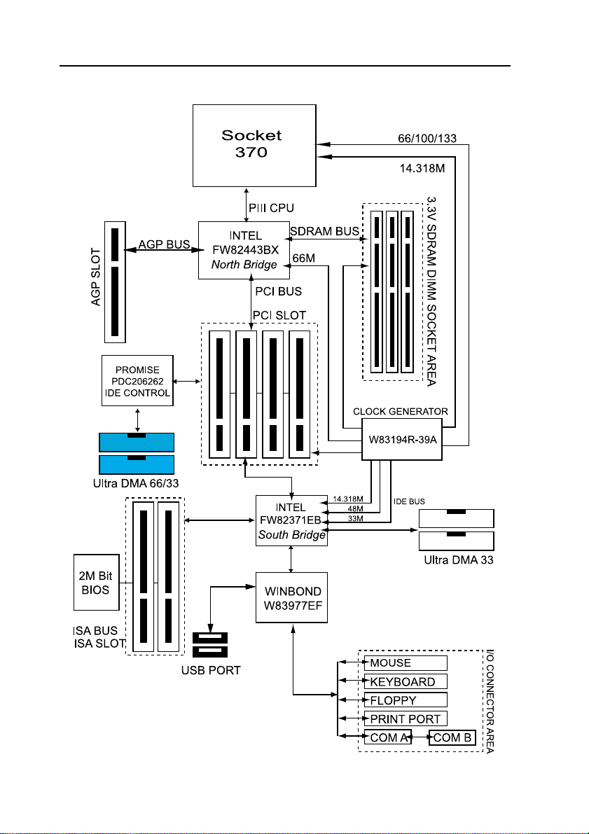
Chipset - Intel FW82443BX AGPset North Bridge.
- Intel FW82371EB South Bridge.
Clock Generator
- Supports 66 / 100 / 133* MHz.
( "*" means frequency can be adjusted, and subject to different
configuration )
Memory - 3 x 168-pin DIMM Sockets.
- Supports 100MHZ & 133MHZ SDRAM 16MB~768MB.
- Supports only 3.3V SDRAM DIMM.
Introduction

6
3IBAT User’s Manual
I/O Control
- Winbond W83977EF-AW
PCI Ultra DMA66 EIDE Controller
- Promise Chipset supports 2 channels Ultra DMA66/33 IDE
Port for 4 IDE Device.
- Sustained transfer rates up to 66MB/sec.
- PCI “Plug & Play” compatibility.
- Onboard BIOS with LBA translation and Extended Int 13
supporting IDE hard drives up to 128GB.
Expansion Slot
- Four 32-bit PCI slots support Master mode.
- One AGP 2X Slot.
- Two ISA Slot.
I/O Interface
- PCI Bus master IDE interface on board with four connectors
support 8 IDE devices in 4 channel, the PCI IDE Controller
supports PIO Mode 0 to Mode 4, Bus master IDE DMA Mode 2
and Ultra DMA 33/66.
- On board super Multi-I/O chip that support 2 serial port with
16550 Fast UART compatible, 1 parallel port with EPP and
ECP capabilities, and a floppy disk drive interface.
- On board support PS/2 mouse Connector.
- On board support PS/2 Keyboard Connector.
- On board 2 USB ports.
- On board IrDA connector.
- Floppy port supports 2 FDD with 360K, 720K,1.2M,1.44M and
2.88M bytes ,Supports LS-120 floppy disk device.
Other Function
- Support Modem Ring Power On.
- Supports Keyboard, and WOL (Wake On LAN).
Power Supply
- On board 3V, 5V and 12V 20-pin ATX power connector.
- Use switching regulator to support CPU core voltage.

7
3IBAT User’s Manual
Hardware Monitor
- CPU/Power Supply/Chassis Fan Revolution detecting.
- CPU Fan Control.
- System Voltage Detect.
- Display Actual Current Voltage.
BIOS - Licensed AWARD BIOS, 2M bit FLASH RAM.
- ACPI ready for PC98/Windows 98.
-SystemBIOS supportsACPIfunctionandGreen featurefunction,
DMI, Plug and Play Flash ROM.
Form factor
- ATX Form Factor.
- Dimensions 305mm x 190mm, 4 layers PCB.
Drivers - INF Update Utilities.
- Promise Chipset Ulart DMA66/33 IDE drivers.
- Virus Protection Applications.
1-3 PACKAG CH CKLIST
If you discover any item below was damaged or lost, please contact your
vendor.
The main board.
This user manual.
One Floppy disk drive cable.
One Ultra DMA/66 IDE cable.
Software utilities.
8
3IBAT User’s Manual
1-4 Block Diagram
9
3IBAT User’s Manual
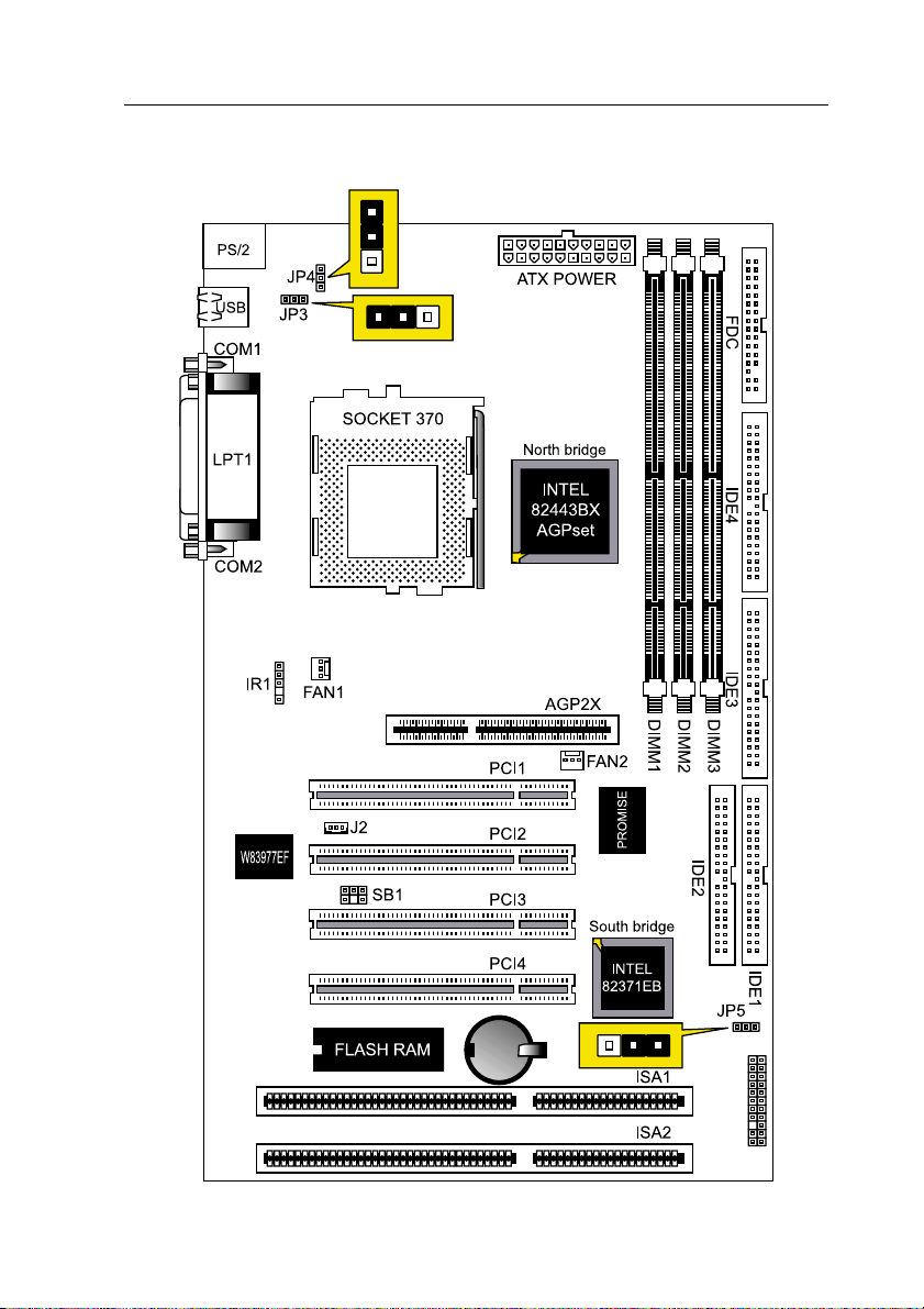
1-5 Main Board Layout with Default Setting
System default support PIII(100/133MHz FSB)

10
3IBAT User’s Manual
1-6 Static lectricity Precautions
Static electricity can easily damage your motherboard.
Observing a few basic precautions can help you safeguard against dam-
age that could result in expensive repairs. Follow the measures below to
protect your equipment from static discharge:
Keep the motherboard and other system components in their antistatic
packaging until you are ready to install them.
Touch a grounded surface before you remove any system component from
its protective antistatic packaging. A grounded surface within easy reach
is the expansion slot covers at the rear of the system case. or any other
unpainted portion of the system chassis.
During configuration and installation, touch a ground surface frequently to
discharge any static electric charge that may build up in your body. An-
other option is to wear a grounding wrist strap.
When handling a motherboard or an adapter card, avoid touching its
components.Handlethemotherboardandadaptercardseitherbythe edges
or by the mounting bracket that attaches to the slot opening in the case.
Table of contents
Other AMPTRON Motherboard manuals

AMPTRON
AMPTRON PM-9800 User manual

AMPTRON
AMPTRON 3WMV Series User manual

AMPTRON
AMPTRON M585LMR User manual

AMPTRON
AMPTRON PIII-3754LMR User manual

AMPTRON
AMPTRON BKS630E User manual

AMPTRON
AMPTRON M810D Series User manual

AMPTRON
AMPTRON PII-3100 User manual

AMPTRON
AMPTRON PM8400B User manual

AMPTRON
AMPTRON M817 Series User manual

AMPTRON
AMPTRON M810LR User manual


