akira MC-6320 User manual

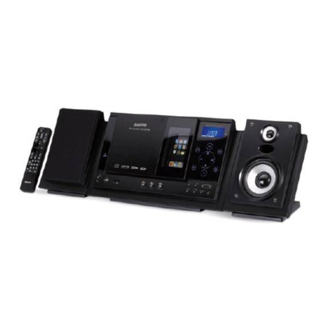
Micro-Mini Compo
Service Manual

2
Model No.: MC-6320
Version: 1.0
MODEL:
MC-6320

3
Model No.: MC-6320
Version: 1.0
CONTENTS
SPECIFICATION..................................................................................................................................... 4
ALIGNMENT INSTRUCTION............................................................................................................... 5
ALIGNMENT CHART ............................................................................................................................ 6
CIRCUIT DIAGRAMS............................................................................................................................ 9
BOM LIST ............................................................................................................................................. 10
EXPLODED VIEW................................................................................................................................ 21
PART LIST............................................................................................................................................. 22

4
Model No.: MC-6320
Version: 1.0
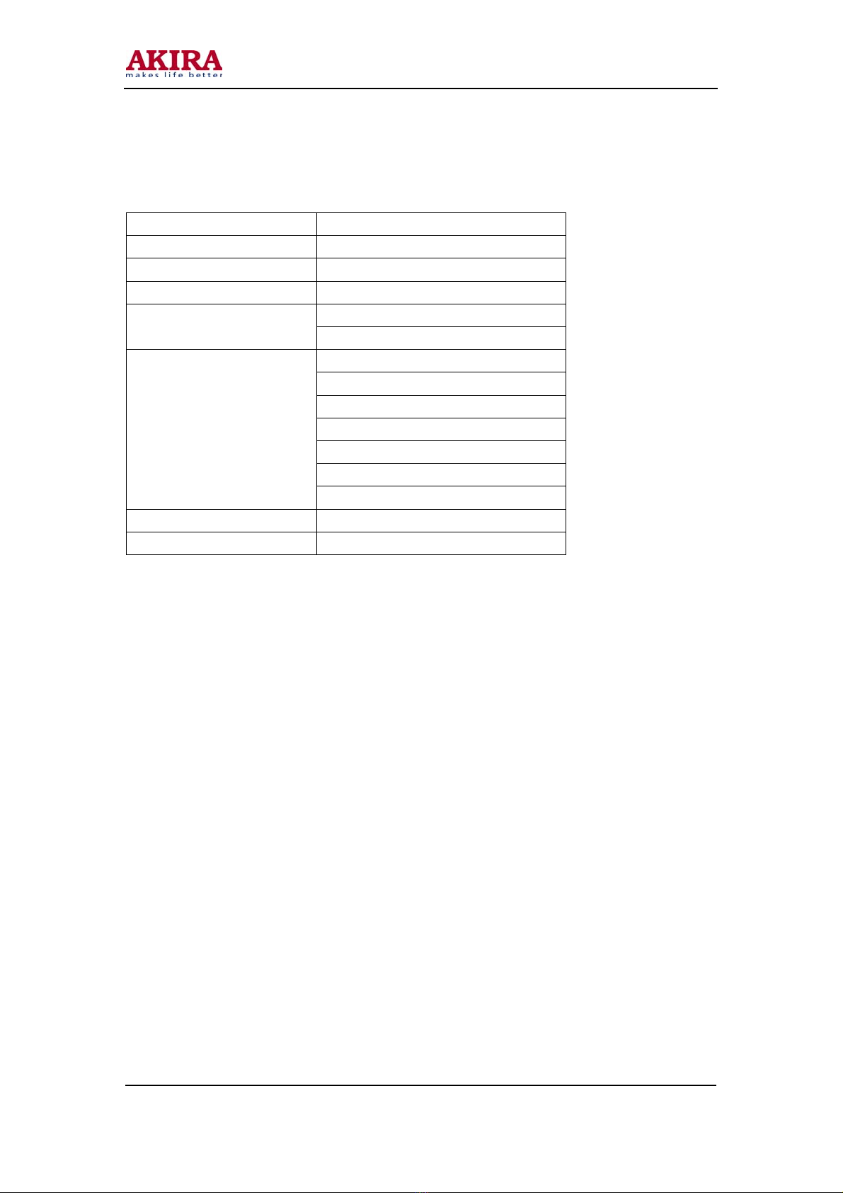
SPECIFICATIONS
Frequency response 100Hz-10kHz
Signal-to-noise ratio 40dB
Output power 4.5W +4.5W
Power consumption 29W
Speaker: 4ohmsTerminal impedance
Headphone: 32Ohms
AC 117V/ 60Hz
AC 220V /50Hz
AC 230V /50Hz
AC 240V /50Hz
AC 110V/ 220V 60Hz /50Hz
AC 110/230V-240V 60Hz/50Hz
Power source
AC 127V /240V 60Hz /50Hz
Dimension 600(L) x 535(D) x 263.5(H)mm
Weight Approx 6.3Kg

5
Model No.: MC-6320
Version: 1.0
ALIGNMENT INSTRUCTION
TEST EQUIPMENT
1. AM signal generator with test loop.
2. FM signal generator.
3. AM/FM-IF signal generator with 455 KHz and 10.7 MHz marker.
4. Oscilloscope with a wide band amplifier of approximately 100 KHz.
5. V.T.V.M ( Vacuum-tube voltmeter ).
6. Power supply.
AM ALIGNMENT
1. Turn on AM signal generator, IF generator, VTVM, oscilloscope and power supply.
2. Using the test loop across the output of MW signal generator, the radio will receive the generator
signal by induction.
3. Connect the VTVM, oscilloscope and 4 ohm dummy load to the Speaker terminal.
4. Set the Band Switch to AM position in sequence.
5. Set the Volume Control to max. Position.
6. Set signal generator frequency as listed in AM Alignment Chart and maintain a sufficient output
level to provide an obvious indication.
7. Proceed as listed in Alignment Chart.
FM-IF ALIGNMENT
1. Set the Selector Switch to FM position.
2. Connect a capacitor 0.1Uf between the PIN1 of IC 1 and the "+VE" output of FM-IF signal
generator. The "-VE" pole of FM-IF signal generator connect to GND.
3. Connect a capacitor 0.1UF between the PIN17 of IC 1 and the "+VE" input of signal generator.
The "-VE" pole of FM-IF generator connect to GND.
FM-RF ALIGNMENT
1. Turn on FM signal generator, VTVM, oscilloscope and power supply.
2. Input the signal to FM ANT.
3. Connect the VTVM, oscilloscope and 4 ohm dummy load to the Speaker terminal.
4. Set the Volume Control to max. Position.
5. Set the Signal Frequency as listed in FM Alignment Chart and maintain a sufficient output level
to provide an obvious reading.

6
Model No.: MC-6320
Version: 1.0
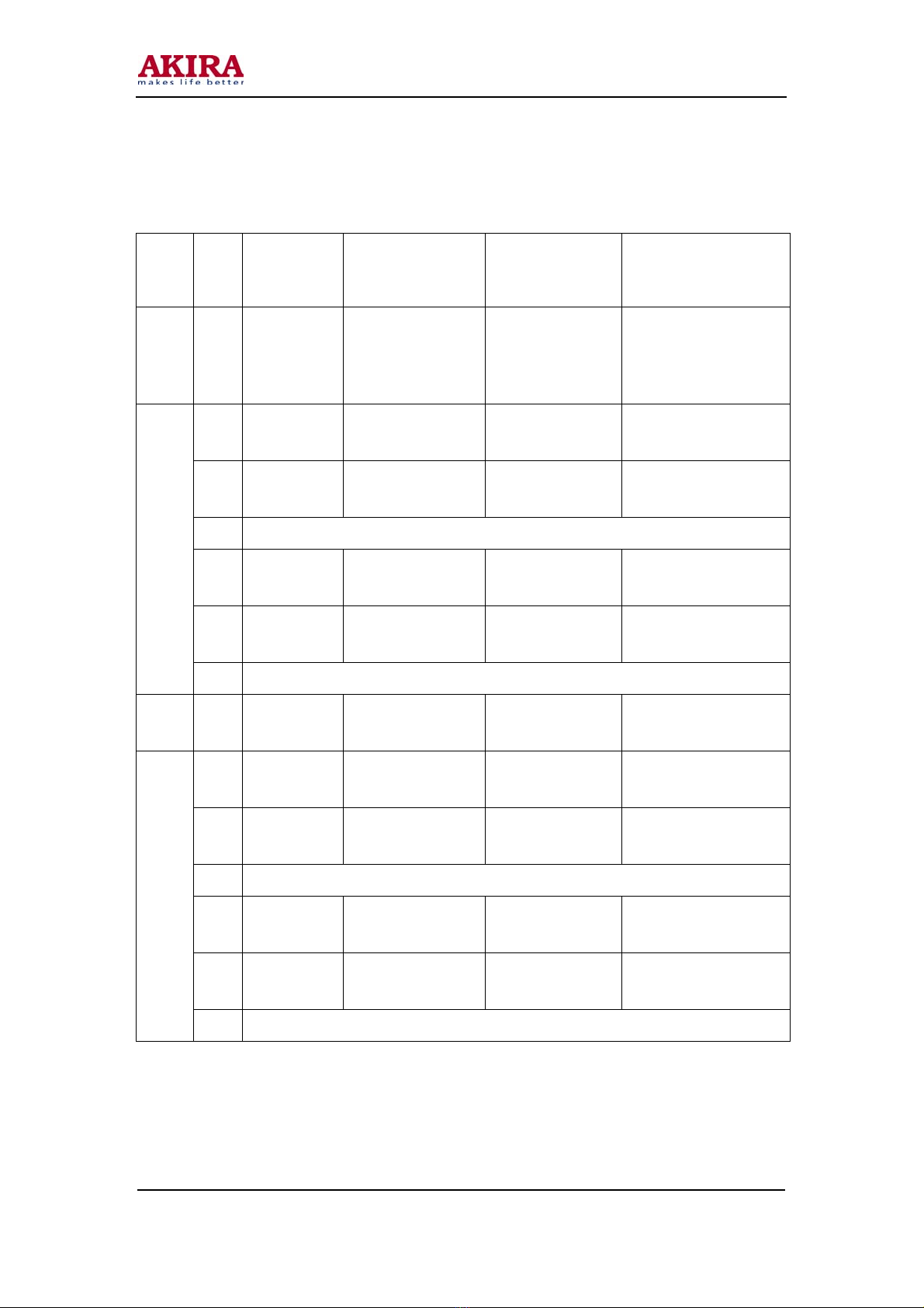
ALIGNMENT CHART
Band Step
Signal
Generator
Frequency
Radio Dial
Setting Adjustment Remark
IF 1 455KHz T8
Adjust for best IF
wave
Form(at detector
output)
1 525KHz
Tuning Gang max.
capacity T5 Adjust for max.
Indication
2 1650KHz
Tuning Gang min.
capacity Trimmer of pvc Adjust for max.
Indication
3 " repeat steps 1 and 2 as required "
4 600KHz Tune to signal
(600KHz) AM ANT COIL Adjust for max.
Indication
5 1400KHz Tune to signal
(1400KHz) Trimmer of pvc Adjust for max.
Indication
AM
6 " repeat steps 4 and 5 as required "
FM-I
F 1 10.7MHz T7 Adjust for best IF
wave Form & S curve
2 87.35MHz
Tuning Gang max.
capacity L3 Adjust for max.
Indication
3 108.3MHz
Tuning gang min.
capacity Trimmer of pvc Adjust for max.
Indication
4 " repeat steps 2 and 3 as required "
5 90MHz Tune to signal
(90MHz) L2 Adjust for max.
Indication
6 106MHz Tune to signal
(106MHz) Trimmer of pvc Adjust for max.
Indication
FM-
RF
7 " repeat steps 5 and 6 as required "

7
Model No.: MC-6320
Version: 1.0
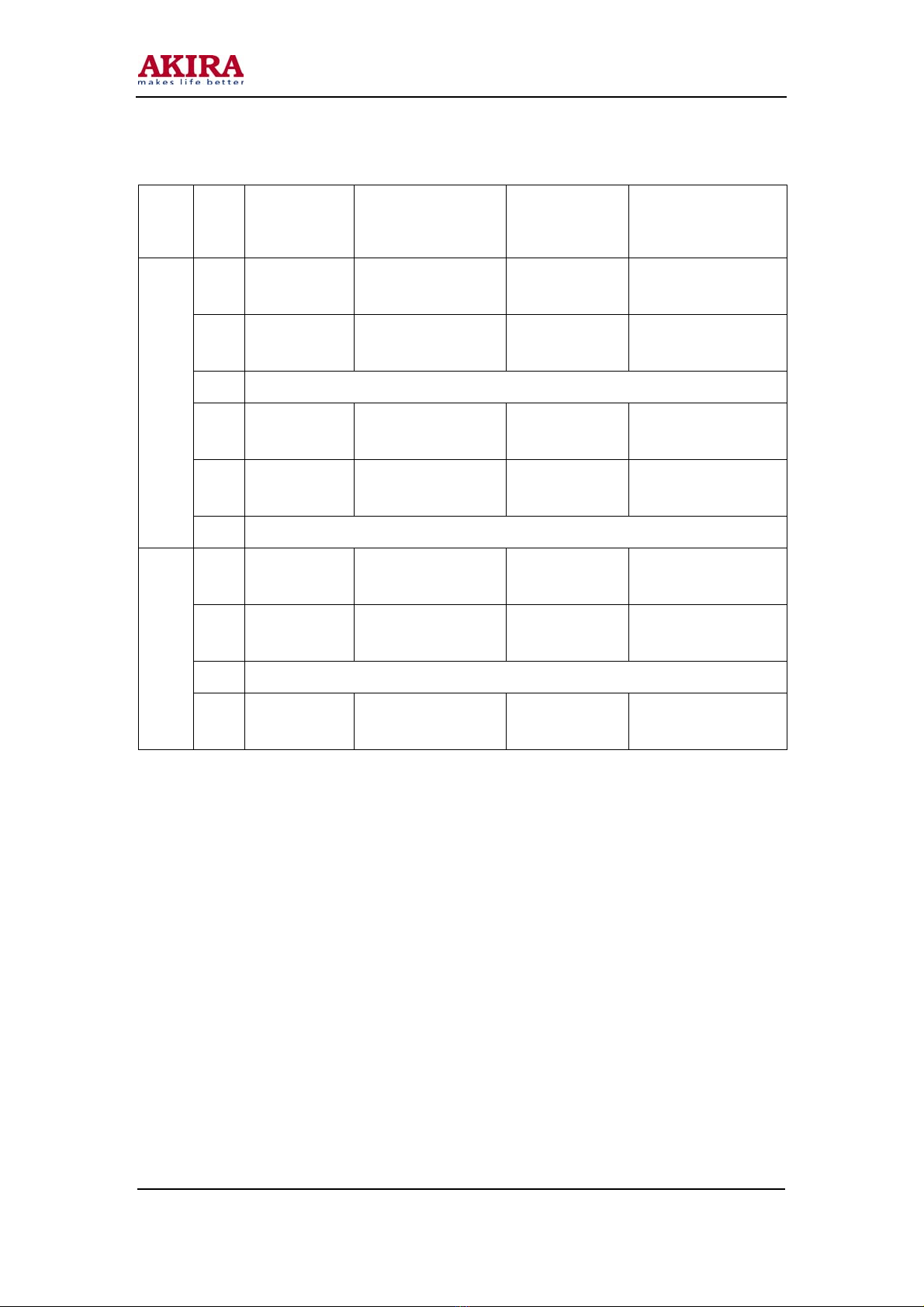
OPTIONAL BAND
Band Step
Signal
Generator
Frequency
Radio Dial
Setting Adjustment Remark
1 150KHz
Tuning Gang max.
capacity T6 Adjust for max.
Indication
2 270KHz
Tuning Gang min.
capacity CT3 Adjust for max.
Indication
3 " repeat steps 1 and 2 as required "
4 170KHz Tune to signal
(170KHz) LW ANT COIL Adjust for max.
Indication
5 250KHz Tune to signal
(250KHz) CT1 Adjust for max.
Indication
LW
6 " repeat steps 4 and 5 as required "
1 3.1MHz
Tuning Gang max.
capacity T6 Adjust for max.
Indication
2 12.25MHz
Tuning gang min.
capacity CT3 Adjust for max.
Indication
3 " repeat steps 2 and 3 as required "
SW
4 3.5MHz Tune to signal
(3.5MHz) T1 Adjust for max.
Indication

8
Model No.: MC-6320
Version: 1.0
CASSETTE SECTION
MOTOR SPEED
Insert 3KHz TEST TAPE to deck compartment and adjust VR of motor to obtain the closing
frequency of 3KHz which is displayed on the frequency counter.
R/P HEAD AZIMUTH
Set the function selection switch to TAPE position.
Tune the volume control to max. output position.
Insert 6.3KHz TEST TAPE into deck compartment. ( TECT MTT-113N )
Adjust the playback head mounting screw to obtain the max. output of frequency 6.3KHz.
Reading at VTVM.
CD SECTION
Connect the VTVM and oscilloscope to the speaker output of the unit.
Put the test disk TCD-781 into the CD compartment.
Set the function selection switch to CD position.
Playback track 1 and set volume position to obtain 1V ( 0 dB ) output from the speaker terminal.
Playback track 6 and track 18 to read the output level which must within specification – 6dB.

9
Model No.: MC-6320
Version: 1.0
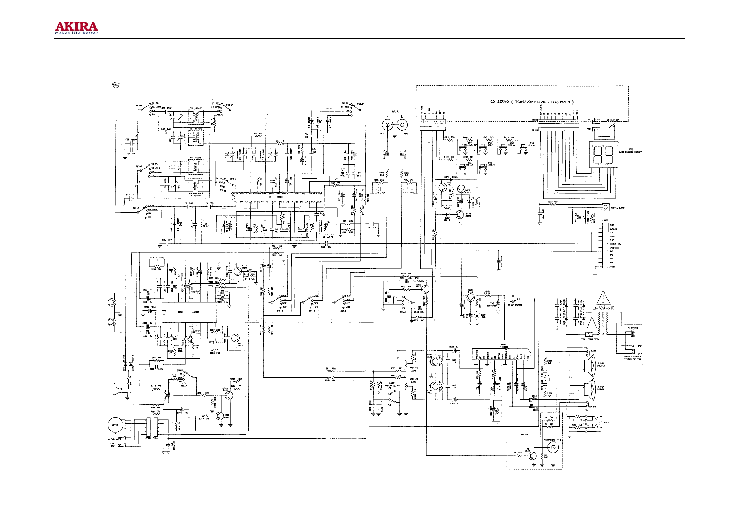
CIRCUIT DIAGRAM

10
Model No.: MC-6320
Version: 1.0
BOM LIST
NUMBER DESCRIPTION PC
101-71-3785-6802 PCB BOARD TS-3785RH-AI REV-0 1
110-53-9014-0320 TRANSISTOR 9014C 5MM 8
110-53-9015-0321 TRANSISTOR 9015C 5MM 2
115-03-0204-1480 DIODE 1N4148 P=26MM 7
192-01-3042-0022 RESISTOR 1/8W +/-5% P=26MM 2.2 OHM 2
192-01-3042-0100 RESISTOR 1/8W +/-5% P=26MM 10 OHM 4
192-01-3042-0220 RESISTOR 1/8W +/-5% P=26MM 22 OHM 1
203-01-0050-0000 JUMPER WIRE D=0.5MM 1
192-01-3042-0470 RESISTOR 1/8W +/-5% P=26MM 47 OHM 5
192-01-3042-1100 RESISTOR 1/8W +/-5% P=26MM 100 OHM 2
192-01-3042-1120 RESISTOR 1/8W +/-5% P=26MM 120 OHM 2
192-01-3042-1150 RESISTOR 1/8W +/-5% P=26MM 150 OHM 2
192-01-3042-1220 RESISTOR 1/8W +/-5% P=26MM 220 OHM 1
192-01-3042-1270 RESISTOR 1/8W +/-5% P=26MM 270 OHM 1
192-01-3042-1330 RESISTOR 1/8W +/-5% P=26MM 330 OHM 1
192-01-3042-2100 RESISTOR 1/8W +/-5% P=26MM 1K OHM 1
192-01-3042-2100 RESISTOR 1/8W +/-5% P=26MM 1K OHM 6
192-01-3042-2220 RESISTOR 1/8W +/-5% P=26MM 2.2K OHM 13
192-01-3042-2270 RESISTOR 1/8W +/-5% P=26MM 2.7K OHM 8
192-01-3042-2330 RESISTOR 1/8W +/-5% P=26MM 3.3K OHM 7
192-01-3042-2470 RESISTOR 1/8W +/-5% P=26MM 4.7K OHM 5
192-01-3042-2510 RESISTOR 1/8W +/-5% P=26MM 5.1K OHM 4
192-01-3042-2560 RESISTOR 1/8W +/-5% P=26MM 5.6K OHM 1
192-01-3042-2560 RESISTOR 1/8W +/-5% P=26MM 5.6K OHM 3
192-01-3042-2680 RESISTOR 1/8W +/-5% P=26MM 6.8K OHM 1
192-01-3042-2820 RESISTOR 1/8W +/-5% P=26MM 8.2K OHM 3
192-01-3042-3100 RESISTOR 1/8W +/-5% P=26MM 10K OHM 13
192-01-3042-3120 RESISTOR 1/8W +/-5% P=26MM 12K OHM 2
192-01-3042-3150 RESISTOR 1/8W +/-5% P=26MM 15K OHM 2
192-01-3042-3220 RESISTOR 1/8W +/-5% P=26MM 22K OHM 2
192-01-3042-3330 RESISTOR 1/8W +/-5% P=26MM 33K OHM 2
192-01-3042-3470 RESISTOR 1/8W +/-5% P=26MM 47K OHM 11

Table of contents
Other akira Stereo System manuals