Acorp 7KMM User manual

The information presented in this publication has been
made carefully for reliability; however, no responsibility
is assumed for inaccuracies. Specifications are subject
to change without notice.
IBM, PC/AT, and PC/XT are trademarks of Interna-
tional Business Machines Corporation.
Athlon is a trademark of AMD Corporation
AWARD is a registered trademark of Phoenix
Sofftware Inc.
MS-DOS and WINDOWS NT are registered trade-
marks of Microsoft Corporation.
Trademarks and/or registered trademarks are the
properties of their respective owners.
User's Manual Version 1.0
7KMM/ 7KMM1
i

Table of Contents
IntroductionIntroduction
Introduction
1. Motherboard Description1. Motherboard Description
1. Motherboard Description
1.1 Features
1.1.1 Hardware 1-2
1.1.2 Software 1-4
1.1.3 Attachments 1-4
1.2 Motherboard Installation
1.2.1 Layout of Motherboard 1-5
1.3 Motherboard Connectors
1.3.1 Front Panel Connectors(PANEL) 1-7
1.3.2 Floppy Disk Connector(FDD) 1-8
1.3.3 Hard Disk Connectors(IDE1/IDE2) 1-8
1.3.4 ATX 20-pin Power Connector(ATX) 1-9
1.3.5 Infrared Connector(IR) 1-9
1.4 Back Panel Connectors
1.4.1 PS/2 Mouse/Keyboard CONN. 1-10
1.4.2 USB Connectors (USB1/USB2) 1-10
1.4.3 VGA Interface Connector(VGA) 1-10
1.5 Serial and Parallel Interface ports 1-12
1.6 CPU Installation
1.6.1 CPU Installation Product(Socket 462) 1-14
1.6.2 CPU Frequency Setting(JCLK) 1-15
1.7 Jumper Setting
1.7.1 CPU Fan Connector(FAN1/2/3) 1-16
1.7.2 Wake-On-Modem Header(WOM) 1-17
1.7.3 Wake-On-LAN Header(WOL) 1-17
1.7.4 Codec Selection(JCOD) 1-17
1.7.5 CMOS Function Selection(CMOS) 1-17
1.8 DRAM Installation
1.8.1 DIMM 1-18
1.8.2 How to install a DIMM Module 1-18
ii

Table of Contents
1.9 Audio Subsystem
1.9.1 CD-Audio-IN Connectors(CDIN1/CDIN2) 1-19
1.9.2 Telephone in Connector(TAD) 1-20
1.9.3 AUX Audio in Connector(AUX) 1-20
1.10 Smart Panel Onboard Connector (option)(option)
(option)(option)
(option)
1.10.1 Port 80 Debug Function(ERR2) 1-22
1.10.2 Second BIOS Connector(JROM) 1-22
1.10.3 Smart Panel Display Function(JGP) 1-22
2. BIOS Setup2. BIOS Setup
2. BIOS Setup
2.1 Main Menu 2-4
2.2 Standard CMOS Features 2-7
2.3 Advanced BIOS Features 2-10
2.4 Advanced Chipset Features 2-14
2.5 Integrated Peripherals 2-19
2.6 Power Management Setup 2-24
2.7 PnP/PCI Configurations 2-30
2.8 PC Health Status 2-34
2.9 Frequency/Voltage Control 2-35
2.10 Load Fail-Safe Defaults 2-36
2.11 Load Optimized Defaults 2-37
2.12 Set Supervisor/user Password 2-38
2.13 Save & Exit Setup 2-40
2.14 Exit Without Saving 2-41
iii

1-11-1
1-11-1
1-1
Chaosdr 1 Mnshdranarc CdrbrhoshnnChaosdr 1 Mnshdranarc Cdrbrhoshnn
Chaosdr 1 Mnshdranarc Cdrbrhoshnn
Introduction
System Overview
This manual was written to help you start using this product
as quickly and smoothly as possbile. Inside you will find
the necessary explanations to solve most problems. In
order for this reference material to be of greatest use, refer
to the “expanded table of contents” to find relevant topics.
This board incorporates the system , I/O , and PCI IDE
into one board that provides a total PC solution. The
mainboard, AMD Athlon and Duron processor base PC
Micro ATX system, support single processors PCI Local Bus,
and AGP Bus to support upgrades to your system
performance.
It is ideal for multi-tasking and fully supports MS-DOS,
Windows, Windows NT , Windows ME, Windows 2000,
Novell, OS/2, Windows95/98, UNIX, SCO UNIX etc.
This manual also explains how to install the mainboard for
operation, and how to setup your CMOS configuration with
the BIOS setup program.

1-11-1
1-11-1
1-1
Chaosdr 1 Mnshdranarc CdrbrhoshnnChaosdr 1 Mnshdranarc Cdrbrhoshnn
Chaosdr 1 Mnshdranarc Cdrbrhoshnn
1.Motherboard Description
1.1 Features
1.1.1 Hardware
CPU
-Single AMD Socket 462 Athlon / Duron.
-200/266MHz System Interface speed.
(266MHz system Only supported by 7KMM1 M/B)
Speed
-Supports 33MHZ PCI Bus speed.
-Supports 4X AGP Bus.
DRAM Memory
-Supports 8/16/32/64....MB DIMM module socket.
-Supports Synchronous DRAM(3.3V)
-Supports a maximum memory size of 1.536GB with SDRAM.
Shadow RAM
-A memory controller provide shadow RAM and supports
8-bit ROM BIOS.
Green Function
-Support power management operation via BIOS.
-Power down timer from 1 to 15 mins.
-Wakes from power saving sleep mode at the press of
any key or any mouse activity.
Bus Slots
-Provide one AGP slot and one AMR slot.
-Three 32-bit PCI bus.

1-31-3
1-31-3
1-3
Chaosdr 1 Mnshdranarc CdrbrhoshnnChaosdr 1 Mnshdranarc Cdrbrhoshnn
Chaosdr 1 Mnshdranarc Cdrbrhoshnn
Universal Serial Bus
-Supports two back Universal Serial Bus(USB)Ports
and two front Universal serial Bus(USB)Ports.
Hardware Monitor Function
-CPU Fan Speed Monitor.
-CPU Temperature Monitor.
-System Voltage Monitor.
Flash Memory
-Support 2/4MB flash memory.
-Support ESCD Function.
IDE Bulit-in On Board
-Supports four IDE devices.
-Supports PIO Mode 5, Master Mode, high performance hard disk
drives.
-Support Ultra DMA 33/66/100 Bus Master Mode.
-Supports IDE interface with CD-ROM.
-Supports high capacity hard disk drives.
-Support LBA mode.
PCI-Based AC 97 Digital Audio Processor
-AC 97 2.1 interface.
-16 channels of high-quality sample rate conversion.
-16x8 channel digital mixer.
-Stereo 10 band graphic equalizer.
-Sound Blaster and Sound Blaster Pro emulation.
WOL/WOM (Wake On LAN & Wake On Modem)
Supports system power up from LAN/Modem ring up .
Smart Panel
Supports BIOS Port 80H POST Code output to debug LED.

1-41-4
1-41-4
1-4
Chaosdr 1 Mnshdranarc CdrbrhoshnnChaosdr 1 Mnshdranarc Cdrbrhoshnn
Chaosdr 1 Mnshdranarc Cdrbrhoshnn
I/O Bulit-in On Board
-Supports one multi-mode Parallel Port.
(1)Standard & Bidirection Parallel Port
(2)Enhanced Parallel Port(EPP)
(3)Extended Capabilities Port
-Supports two serial ports,16550 UART.
-Supports one Infrared transmission(IR).
-Supports PS/2 mouse and PS/2 Keyboard.
-Supports 360KB, 720KB, 1.2MB, 1.44MB, and 2.88MB floppy disk
drivers.
1.1.2 Software
BIOS
-AWARD legal BIOS.
-Supports APM 1.2.
-Supports USB Function.
-Supports ACPI
Operation System
-Offers the highest performance forMS-DOS,Windows,
Windows NT, Windows 2000, Windows ME, Novell, OS/2,
Windows95/98, UNIX, SCO UNIX etc.
1.1.3 Attachments
-HDD UDMA66/100 Cable.
-FDD Cable.
-Flash Memory Written for BIOS Update.
-USB2 Cable (Option) .
-COM2 Cable.
-Fully Setup CD Driver built in Utility(Ghost, Anitivirus,
Adobe Acrobat).
-This Manual.

1-51-5
1-51-5
1-5
Chaosdr 1 Mnshdranarc CdrbrhoshnnChaosdr 1 Mnshdranarc Cdrbrhoshnn
Chaosdr 1 Mnshdranarc Cdrbrhoshnn
1.2 Motherboard Installation
1.2.1 Layout of Motherboard
USB1
COM1
VGA
Printer
FAN2
FAN1
Speak out
Line in
Mic in
GAME1
VIA
VIA
PANEL
FAN3
AMR SLOT
AGP SLOT
CMOS
PCI1
PCI2
PCI3
1
DIMM2
DIMM1
DIMM3
JCOD
JROM
462
ERR2

1-61-6
1-61-6
1-6
Chaosdr 1 Mnshdranarc CdrbrhoshnnChaosdr 1 Mnshdranarc Cdrbrhoshnn
Chaosdr 1 Mnshdranarc Cdrbrhoshnn
USB1
COM1
VGA
Printer
FAN2
FAN1
Speak out
Line in
Mic in
GAME1
VIA
VIA
PANEL
FAN3
AMR SLOT
AGP SLOT
CMOS
PCI1
PCI2
PCI3
1
DIMM2
DIMM1
DIMM3
JCOD
JROM
462
ERR2
1.3 Motherboard Connectors
6
7
18
12
9
4,5
1.Babk OandkI.O Cnnndbsnrr1.Babk OandkI.O Cnnndbsnrr
1.Babk OandkI.O Cnnndbsnrr1.CCAtchn-InCnnndbsnr1.CCAtchn-InCnnndbsnr
1.CCAtchn-InCnnndbsnr1.CCAtchn-InCnnndbsnr
1.CCAtchn-InCnnndbsnr
3.Frnns COM1Cnnndbsnr3.Frnns COM1Cnnndbsnr
3.Frnns COM1Cnnndbsnr 4.Wakd-On MOCDM Cnnndbsnr4.Wakd-On MOCDM Cnnndbsnr
4.Wakd-On MOCDM Cnnndbsnr4.Wakd-On MOCDM Cnnndbsnr
4.Wakd-On MOCDM Cnnndbsnr
5.Wakd-On-LAN Cnnndbsnr5.Wakd-On-LAN Cnnndbsnr
5.Wakd-On-LAN Cnnndbsnr 6.Frnns USB1Cnnndbsnr6.Frnns USB1Cnnndbsnr
6.Frnns USB1Cnnndbsnr6.Frnns USB1Cnnndbsnr
6.Frnns USB1Cnnndbsnr
7.Frnns OandkCnnndbsnr7.Frnns OandkCnnndbsnr
7.Frnns OandkCnnndbsnr 8.FanCnnndbsnrr(Fan1.1.3(8.FanCnnndbsnrr(Fan1.1.3(
8.FanCnnndbsnrr(Fan1.1.3(8.FanCnnndbsnrr(Fan1.1.3(
8.FanCnnndbsnrr(Fan1.1.3(
9.ICD Cnnndbsnrr9.ICD Cnnndbsnrr
9.ICD Cnnndbsnrr10.Fknooy Cnnndbsnr10.Fknooy Cnnndbsnr
10.Fknooy Cnnndbsnr10.Fknooy Cnnndbsnr
10.Fknooy Cnnndbsnr
11.COU Cknbk Sdkdbshnn(JCLJ(11.COU Cknbk Sdkdbshnn(JCLJ(
11.COU Cknbk Sdkdbshnn(JCLJ( 11.IR Cnnndbsnr11.IR Cnnndbsnr
11.IR Cnnndbsnr11.IR Cnnndbsnr
11.IR Cnnndbsnr
13.ATX Onwdr Cnnndbsnr13.ATX Onwdr Cnnndbsnr
13.ATX Onwdr Cnnndbsnr 14.COCDC Sdkdbshnn(JCOC(14.COCDC Sdkdbshnn(JCOC(
14.COCDC Sdkdbshnn(JCOC(14.COCDC Sdkdbshnn(JCOC(
14.COCDC Sdkdbshnn(JCOC(
15.Slars OandkFtnbshnn(DRR1.JROM.JFO((noshnn(15.Slars OandkFtnbshnn(DRR1.JROM.JFO((noshnn(
15.Slars OandkFtnbshnn(DRR1.JROM.JFO((noshnn(
16.Tdkdohnnd hn Cnnndbsnr(TAC(16.Tdkdohnnd hn Cnnndbsnr(TAC(
16.Tdkdohnnd hn Cnnndbsnr(TAC(
17.AUX Atchn hn Cnnndbsnr(AUX(17.AUX Atchn hn Cnnndbsnr(AUX(
17.AUX Atchn hn Cnnndbsnr(AUX(
18.CMOS FtnbshnnSdkdbshnn(CMOS(18.CMOS FtnbshnnSdkdbshnn(CMOS(
18.CMOS FtnbshnnSdkdbshnn(CMOS(
1
10
8
2
16 14
11
15
17
15
3
13
15

1-71-7
1-71-7
1-7
Chaosdr 1 Mnshdranarc CdrbrhoshnnChaosdr 1 Mnshdranarc Cdrbrhoshnn
Chaosdr 1 Mnshdranarc Cdrbrhoshnn
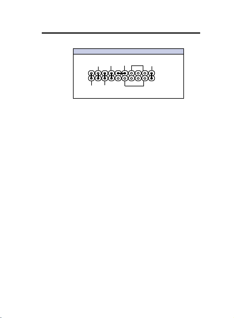
1.3.1 Front Panel Connector(PANEL)
PANEL Connector
Speaker Connector (SPEAKER)
An offboard speaker can be installed onto the motherboard as a
manufacturing option. An offboard speaker can be connected to
the motherboard at the front pannel connector. The speaker
(onboard or offboard) provides error beep code information dur-
ing the Power Self-Test when the computer cannot use the video
interface. The speaker is not connected to the audio subsystem
and does not receive output from the audio subsystem.
Hard Drive LED Connector (HDLED)
This connector supplies power to the cabinet IDE activity LED.
Read and write activity by devices connected to the Primary or
Secondary IDE connectors will cause the LED to light up.
SMI Suspend Switch Lead (EXTSMI)
This allows the user to manually place the system into a suspend
mode or Green mode where systematic activity will be instantly
decreased to save electricity and expand the life of certain com-
ponents when the system is not in use. This 2-pin connector
(see the figure below) connects to the case-mounted suspend
switch. If you do not have a switch for the connector, you may
use the Turbo Switch” instead since it does not have a function.
SMI is activated when it detects a short to open moment. It may
require one or two pushes depending on the position of the
switch. Wake-up can be controlled by settings in the BIOS but
the keyboard will always allow wake-up (the SMI lead cannot
wake-up the system). If you want to use this connector, the
"Suspend Switch" in the Power Management Setup of the BIOS
SOFTWARE section should be on the default setting of Enable.
SPEAKER
PW_BN
1
2
RESET
EXTSMI
HDLED PW_LED
+
+
+
+
S3_LED
SLPBTN
++
This manual suits for next models
1
Table of contents
Other Acorp Motherboard manuals

Acorp
Acorp 4D533 User manual

Acorp
Acorp 7KT400ANL User manual

Acorp
Acorp 6M810D User manual

Acorp
Acorp 6M810E2 User manual

Acorp
Acorp 7KM400QP User manual

Acorp
Acorp 6A815EPQ User manual

Acorp
Acorp 4S651M User manual

Acorp
Acorp 6A815EP1 User manual

Acorp
Acorp 4S845AL User manual

Acorp
Acorp 4PX266A User manual