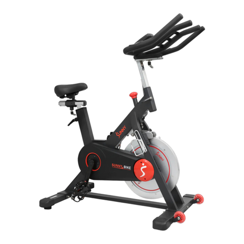
YESOUL S3 PLUS User manual

Before using this product,
carefully read
and properly keep this manual.
S3PLUS
YESOUL BIKE
S3PLUS Product Manual
Product model: YS-001
YESOUL BIKE

Product Parameters
Screen size
Supporting software version
Resistance system
Drive mode
Power supply
Height limit
Rated maximum load
Net weight
Gross weight
Overall dimensions
21.5 inches (1920×1080 pixels)
Android
Magnetron resistance system
Belt drive
12V power adapter
150~195cm
120kg
38.5kg
42.8kg
(length) 1130mm × (width) 520mm × (height) 1230 mm
YESOUL BIKE S3PLUS

Please read them carefully. Improper use may result in
personal injury or death!
1. Make sure that the saddle height adjustment knob is secured correctly, and will not affect
motion during exercise.
2. Keep children and pets away from this product. This product is for those over 16 years old
only.
3. Never stretch any object or body part into the openings of the bike.
4. The weight of the user must not exceed the maximum load.
5. Get off the bike until flywheel and pedals stop rotating. Otherwise, severe injuries may be
caused due to control failure.
6. If you feel any discomfort, such as dizziness or breathing difficulty, stop riding the bike and
carefully get off.
7. Never turn pedals by hand or touch any rotating mechanical part; otherwise, personal
injury may be caused.
8. Keep the body hydrated as needed during riding.
9. Use this product according to the instructions in this manual. Warm up fully before exercise.
10. Without the preliminary determination of baseline fitness level and medical certificate
signed by a doctor, never be engaged in high-speed or high-intensity sports. Before attempt-
ing any high-intensity short sprints, pay attention to the body state and posture, and apply a
controllable speed.
11. Wear professional cycling clothes or tight-fitting sportswear and sports shoes, and tighten
foot straps to avoid injury caused by pulling or entanglement by this product.
12. Never use this product with inappropriate shoes or barefoot.
13. Incorrect or excessive training may cause injury.
14. Check whether the bike for loosening or damage before each use.
15. Never refit this bike or use non-original accessories without permission. The casing must
be opened by professionals, in order to avoid damage.
16. Those pregnant or with high blood pressure, heart disease, lumbar spondylosis or reduced
mobility must not use this product without the permission of doctors.
17. In case of any discomfort such as dizziness or chest pain during exercise, stop exercising
immediately and go to a hospital for examination.
18. If the product fails, immediately stop using it.
19. This product must not be used for medical rehabilitation.
20. Use this product on a flat and clean ground.
21. Carry out preventive maintenance regularly.
22. Never expose this product in a humid place. This product must not be used outdoor or in
any humid place.
Important Safety Instructions

Display holder
Decorative cover
⑦1
2 × hexagon socket
button head screw
M8 × 45/washer
2 × hexagon socket
button head screw
M8 × 45/washer
Installation Guide - List of Parts
STEP 1: Check of parts
List of Parts
Parts List (Components List)
NO. Name
Frame
Handlebar
Pedal set left/right
Front tube
Rear tube
Quantity Picture
②
③
④
1
1
1
①1
(L) (R)
⑤
⑥
1
1
21.5 Screen
⑧1

*In order to facilitate assembly, some accessories have been installed on the body before
delivery.
Installation Guide - List of Parts
Parts List (Components List)
Hexagon socket
cap screw M8×45
NO. Name Quantity Picture
⑩1
Accessories List (Tools List)
Hex wrench, 4#
Hex wrench, 5#
L-type cross
head hex wrench, 6#
Open-ended wrench (8#)
NO. Name Quantity Picture
A
B
C
D
1
1
1
1
Open-ended wrench
E1
6.2 12V power adapter
⑨1

Washer
STEP 2: Installation of bottom tube
Installation Guide
1. Take L-type cross head hex wrench 6# (D) out of the ziplock bag.
2. Remove four hexagon socket button head screws (M8 × 45) and washers of the front tube ② and
rear tube ③ via the L-type cross head hex wrench 6# (D).
3. Align the holes of the front and rear front tube ② and rear tube ③ with the bottom holes of the
frame ①, manually screw the washers and hexagon socket button head screws (M8×45), and tighten
then via the L-type cross head hex wrench 6# (D).

A
STEP 3: Installation of handlebar assembly
1. Remove four hex bolts from the head tube.
2. Align the connection holes of handlebar assembly, and manually turn screws into four holes
(without tightening).
Insert the display holder into the round hole of the handlebar as indicated by the arrow, and
correctly align the holes.
Manually turn the other long hex bolt (in the tool kit) into the corresponding holes.
Finally, tighten all bolts via the hex wrench5# (C).
Installation Guide

GasketDisk-type
spring washer
STEP 4: Display fixing
1. Remove the original bolts, nuts, four disk-type spring washers and one gasket from the
handlebar via the hex wrench 4#(B).
2. Align the rear holes of the display with the holes of the handlebar, and reinstall the bolt, nut,
four disk-type spring washers and one gasket in the original order. While fixing the bolt with
the hex wrench4# (B), tighten the nut as indicated by the arrow via the open-ended wrench 8#
(A).
*The curved surfaces of disk-type spring washers are slightly bent. Please install these
spring washers in the same direction.
Installation Guide

Open-ended wrench(E)
(in the ziplock bag)
STEP 5: Pedal installation
Reverse riding is not recommended, as it is likely to loosen pedals. After reverse riding,
check whether the pedals are locked, in order to avoid safety issues arising from loose
pedals.
Safety tips:
Installation Guide
1. Take out the pedal assembly ④.
2. Pay attention to distinguish left pedal and right pedals.
3. Lock the pedal assembly L ④ into the left crank, and tighten with the box-ended wrench ( E) along
the direction indicated by the arrow.
4. Lock the pedal assembly R ④ into the right crank, and tighten with the box-ended wrench (E) along
the direction indicated by the arrow.
Pedal assembly
L ④
Pedal assembly
R ④

+
-
Rear column tightening knob
(Adjust the saddle height)
Front column tightening
knob(Adjust the head
height)
Lockable pulley
Saddle tightening knob
(Adjust the saddle
horizontally)
Saddle tightening knob
(Adjust the saddle
horizontally)
Low
High
Resistance knob
(Adjust the resistance as needed;
press it to brake in an emergency.)
Statement:
This manual contains the functional introduction and operating instructions as much as
possible when printed.
With the continuous improvement of hardware and software and optimization of design, this
manual may be inconsistent with the purchased product.
In case of any discrepancy in appearance, interface and color, the actual product shall prevail.
Safety tips:
Reverse riding is not recommended, as it is likely to loosen pedals. After reverse
riding, check whether the pedals are locked, in order to avoid safety issues arising
from loose pedals.
Installation Guide (the following instructions are for reference only; the actual product will prevail)
This manual suits for next models
1
Table of contents
Other YESOUL Exercise Bike manuals