Wireless Devices POCSAG Y1707RS User manual

1
POCSAG Wireless Data Receiver
Model No. Y1707RS/TTL
Operation Manual
Wireless Devices Inc. (Taiwan)
2
Multi-Function Radio Paging Data Receiver, Model No:Y1707RS/TTL
The Y1707 Series is the high performance VHF/UHF/900MHz paging data receiver which is an
ideal product for providing remote control and one way telemetry utilizing either the existing
POCSAG paging infrastructure or on-premises paging equipment. These units provide eight
addressable TTL output lines as well as a RS-232 serial port output.
Application
•Data Receiver
•Remote Controller
•Car Burglar Alarm
•Telemetry
•Data Monitor
•Advertisement Panel
•Taxicab Call message
•LED Display Panel
•Any remote application
Main Function
•138MHz~174MHz, 430MHz~470MHz, 929MHz~933MHz
•POCSAG, Baud: 512bps/1200bps/2400bps
•Built-in RS-232 Driver
•Built-in 6 Ports On/Off Output to Driver Relays
•Data output TTL or RS-232 Output
•Numeric( 4bit) / Alphanumeric (7bit) selectable
•Over the Air to Reprogramming Pager ID and Password
•Programming by RS-232 from P/C Windows
•Internal Antenna For Long distance

3
Specifications
General
Size:
70mm X 50 mm X 18 mm (Module only without Housing)
76mm X 72mm X 33mm (with Housing)
Power supply requirements: 6-13V DC. 50mA maximum current consumption.
Weight 30gm(Module only) / 60gm (with housing)
Operation Temperature -40˚C~85˚C
RF Performance
Frequency bands:
138~174MHz,(synthesize), 430~470/929~932MHz by crystals
Oscillator
No-tune bandwidth: 10Mhz VHF, 20MHz UHF.
Frequency stability: +/- 2.5ppm standard
Channel spacing 12.5kHz or 25kHz
Demodulation FSK NRZ, POCSAG format 512, 1200 or 2400 Bps
Selectivity 55dB
Inter modulation rejection 60dB
PLL step size 12.5K/25K
Sensitivity -106db/M (512bps),-105db/M (1200bps), -103db/M (2400bps)
User Interfaces
Serial RS-232 -2400 Bps
Parallel 8 discrete outputs, TTL levels.
Programming Via serial port or Over the Air Reprogramming.
Antenna Built-in loop antenna
Output port ULN-2003 Low for active

4
Model No: Y1707RS/TTL
Pin and Connector Designation
V+
GND Power
O/1
O/2
O/3
O/4
O/5
O/6
RXD(RS232)
TXD(RS232)
GND(RS-232)
V+
V+ 6~13V Power
GND
8 7 6 5 4 3 2 1
16 15 14 13 12 11 10 9
TOP
2.54X8X2
J2 Main Connector
TXD(TTL)
RXD(TTL)
ON/OFF/PULSE Outpou Port 1~6
Receiver Data output to P/C DB9-pin #2
Data input from P/C to P/C DB9- pin #3
TTL Data Output(Option)
TTl Data Input(Option)
1
2
3
4
5
6
7
8
9
10
11
12
13
14
15
16
Red Power
Green On-Air
Phone Jack RS-232
DC Jack
J1J3LED
RY1
RELAY-DPDT
RY6
RELAY-DPDT
+12
Any DC 12 V Relays
System ground to P/C DB9- pin #5
Remoto Controller Application Section
Data Application Section

5
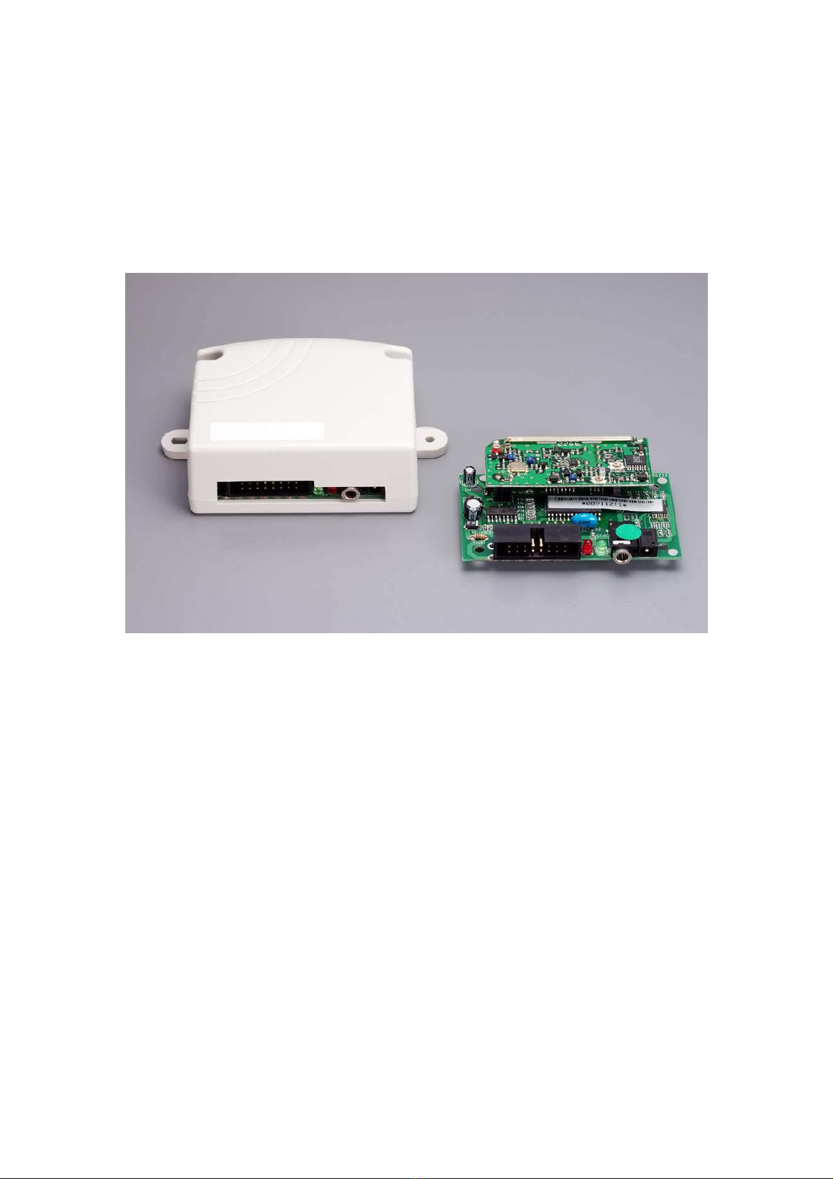
◎J1 DC Jack for DC Power 6~13 V Input.
◎J3 (Phone Jack) RS-232 Connect with Computer for POCSAG Data receiver Use Only.
◎Green color, LED for Paging network signal Indicate.
◎Red color, LED for Power ON Indicate.
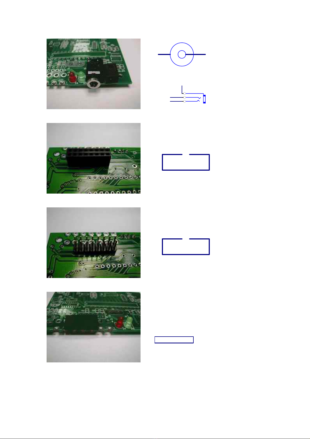
◎J2 Main connector for multi input/output and power connect with Computer or Relays, also
to Connect with computer to programming.
J2-1 O/1 for Port #1 output to drive to relays.
J2-2 O/2 for Port #2 output to drive to relays.
J2-3 O/3 for Port #3 output to drive to relays.
J2-4 O/4 for Port #4 output to drive to relays.
J2-5 O/5 for Port #5 output to drive to relays.
J2-6 O/6 for Port #6 output to drive to relays.
J2-7, 8,16 for DC power Input DC 6~13 V+.
J2-9, 10 System ground for power V-.
J2-11 Ground for RS-232. (Connect with Computer Pin 5 of RS-232 DB9).
J2-12 TXD for data output. (Connect with Computer Pin 2 of RS-232 DB9).
J2-13 RXD, for data input. (Connect with Computer Pin 3 of RS-232 DB9).
J2-14 TXD (TTL level output)(for option).
J2-15 RXD (TTL level input)(for option).

6
Y1707RS/TTL [Version 1.3]
<<Remote Controller’s Application Sections >>
A. How to issue the command to your paging remote controller
Please access a paging call attempt with the following messages.
PPPP A C C RRRRR
Preventing the incorrect key inputs [PPPP + ACC + RRRRR = 12 Digits (must)].
PPPP = Password (0001~9999)
A= Output Port Number.
A=1 = Relay #1.
A=2 = Relay #2.
A=0 = Relay #1 + Relay #2.
CC = Output Status (Remark: H=Relay Active, L=Off, T=Times, Z=Endless)
00 = Always L
01 = Always H
12 = H2S/1T
13 = H1S/L1S/3T
14 = H2S/L2S/4T
15 = H10S/L10S/Z
16 = H20S/L20S/Z
17 = H1S/ L1S/Z
18 = H0.5S/L0.5S/Z
19 = H6S/L1S/Z
21 = H0.25S/L10S/H0.5S/L10S/H1S/L10S/H2S/L10S/H.Z
22 = H0.5S/1T
23 = H3S/1T.
24 = H20S/1T.
25 = H3S/L3S/10T.
26 = H2S/L2S/20T.
27 = H1S/L1S/30T.
28 = H0.5S/L0.5H/30T.
29 = H30S/1T.
31 = H0.5sec/1T
32 = H1sec/1T
33 = H3sec/1T
34 = H5sec/1T
35 = H8sec/1T
36 = H10sec/1T

7
37 = H12sec/1T
38 = H30sec/1T
39 = H50sec/1T
41 = H1min/1T
42 = H3min/1T
43 = H5min/1T
44 = H8min/1T
45 = H10min/1T
46 = H15min/1T
47 = H20min/1T
48 = H30min/1T
49 = H45min/1T
51 = H1hr/1T
52 = H2hr/1T
53 = H3hr/1T
54 = H4hr/1T
55 = H6hr/1T
56 = H8hr/1T
57 = H12hr/1T
58 = H13hr/1T
59 = H24hr/1T
If A C C = 0 0 0 = All Relays Off.
RRRRR = Customer ID. These 5 digital ID are to secure the correct message
commands, which must only be set by via the P/C programming.
Example for making the command:
Message: 2222 1 01 12345
Password = 2222 (PPPP)
1 = Relay # 1 (A)
01 = ON (CC)
12345 = customer ID, (RRRRR)

8
B. How to Change the Password
Please make a paging call attempt with the messages as below.
PPPP NNNN PPPP
PPPP = Old Password (0001~9999)
NNNN = New Password
PPPP = Old Password (0001~9999)
Preventing the incorrect key inputs [PPPP + ACC + RRRRR = 12 Digits (must)].
Example for changing the password:
1111 2222 1111
Old Pass word = 1111 (PPPP)
New Pass Word = 2222 (NNNN)

9
The several types for Y1707 Module Connectors to meet with difference application
Type S V+ 6-24V
GND Power
O/1
O/2
O/3
O/4
O/5
O/6
RXD(RS232)DB9-3
TXD(RS232)DB9-2
GND(RS-232)DB9-5
V+ 6-24V
V+ 6-24V
GND Power
8 7 6 5 4 3 2 1
16 15 14 13 12 11 10 9
SIDE
TOP
2.54X8X2
J2
TXD(TTL for option
)
RXD(TTL for option
)
1
2
3
4
5
6
7
8
9
10
11
12
13
14
15
16
Type 1 V+ 6-24V
GND Power
O/1
O/2
O/3
O/4
O/5
O/6
RXD(RS232)DB9-3
TXD(RS232)DB9-2
GND(RS-232)DB9-5
V+ 6-24V
V+ 6-24V
GND Power
8 7 6 5 4 3 2 1
16 15 14 13 12 11 10 9
SIDE
TOP
2.54X8X2
J2
TXD(TTL for option
)
RXD(TTL for option
)
1
2
3
4
5
6
7
8
9
10
11
12
13
14
15
16
Type 2
NC
NC
NC
GND Power
LOOP WITH #11
RS232 RX from PC
ON-Air LED Indica
t
NC
RS232 TX to PC
loop with #4
V+ 6-24V
NC
GND RS-232
GND
1
2
3
4
5
6
7
8
9
10
11
12
13
14
14 13 12 11 10 9 8
7 6 5 4 3 2 1
TOP
SIDE
CP014
J3
Type 3
GND
LOOP WITH #5
RS232 RX from PC
ON-Air LED Indica
t
RS232 TX to PC
loop with #1
V+ 6-24V
NC
1
2
3
4
5
6
7
8
8 7 6 5
4 3 2 1
TOP
SIDE
CP014
J3
10
Type 4
GND
RS-232 RX
RS-232 TX
Power V+ 6-24V
-+
Type 5 V+ 6-24V
GND Power
O/1
O/2
O/3
O/4
O/5
O/6
RXD(RS232)DB9-3
TXD(RS232)DB9-2
GND(RS-232)DB9-5
V+ 6-24V
V+ 6-24V
GND Power
8 7 6 5 4 3 2 1
16 15 14 13 12 11 10 9
SIDE
TOP
2.54X8X2
J2
TXD(TTL for option
)
RXD(TTL for option
)
1
2
3
4
5
6
7
8
9
10
11
12
13
14
15
16
Type 6 V+ 6-24V
GND Power
O/1
O/2
O/3
O/4
O/5
O/6
RXD(RS232)DB9-3
TXD(RS232)DB9-2
GND(RS-232)DB9-5
V+ 6-24V
V+ 6-24V
GND Power
8 7 6 5 4 3 2 1
16 15 14 13 12 11 10 9
SIDE
TOP
2.54X8X2
J2
TXD(TTL for option
)
RXD(TTL for option
)
1
2
3
4
5
6
7
8
9
10
11
12
13
14
15
16
Type 7
RXD(RS232)DB9-3
TXD(RS232)DB9-2
GND(RS-232)DB9-5
V+ 6~24V Power
6 5 4 3 2 1
TOP
2.54 X 6 TXD(TTL for option)
RXD(TTL for option)
J2a
1
2
3
4
5
6
This manual suits for next models
1
Table of contents


