Vanco 280621 User manual

HDBaseT™ Extender
(230ft/70m)
Vanco Part Number:
280621
Technical Support
www.vanco1.com • [email protected] • 800-626-6445

www.vanco1.com 800-626-6445
2
1. Do not expose this unit to water, moisture,
or excessive humidity.
2. Do not install or place this unit in a built-in
cabinet, or other conned space without
adequate ventilation.
3. To prevent risk of electrical shock or re
hazard, due to overheating, do not obstruct
unit’s ventilation openings.
4. Do not install near any source of heat,
including other units that may produce heat.
5. Do not place unit near ames.
6. Only clean unit with a dry cloth.
7. Unplug unit during lightening storms, or
when not used for an extended period
of time. A surge protector is strongly
recommended.
8. Protect the power cord from being walked
on or pinched, particularly at the plugs.
9. Use unit only with accessories specied by
the manufacturer.
10. Refer all servicing to qualied personnel.
CAUTION
HDMI is a very complex technology requiring continuous authentication of the signal and the same
video resolution and audio settings on all electronic equipment in the system. When there are multiple
sources and displays, the video resolution and audio setting on all connected units must be adjusted
to correspond with that of the display having the lowest video and audio capability.
WARNING
DEAR CUSTOMER
Thank you for purchasing this product.
For optimum performance and safety, please
read these instructions carefully before
connecting, operating or adjusting this product.
Please keep this manual for future reference.
This product is 100% inspected and tested in the United States
to verify HDMI performance parameters.

www.vanco1.com 800-626-6445 3
FEATURES
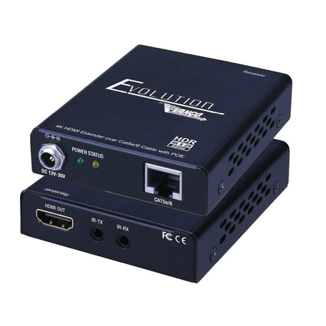
The Vanco 280621 HDMI Extender over Single Cat5e/6 with HDBaseT Technology, Bi-directional
IR, RS-232 and PoE extends high denition video and audio signals, IR, RS-232, and power at
a distance of up to 230ft/70m over a single Cat5e/6 cable. 4K2K (2160p @30hz) resolution
compatible, and can be extended up to 131ft/40m. Features HDBaseT Technology that allows for
greater transmission range compared to standard HDMI extenders. Also features Power over
Ethernet (PoE) Technology which transmits power over Cat5e/6, allowing for either Transmitter
or Receiver to be powered without the use of a power supply. The result is an easy and exible
installation with low maintenance. Deep color video, DTS-HD or Dolby TrueHD audio, and HDCP is
supported and compatible with the 280621. In addition, bi-directional IR pass-through allows for
source or display control. For extending HDMI over a single Cat5e/6 with IR at a long distance,
with plug and play HDBaseT technology, the 280621 is a great solution!
The 280621 includes two units: transmitting unit (280621-TX) and receiving unit (280621-RX).
The transmitting unit is used to capture the HDMI input with IR signals and carries the signals via
one cost effective Cat5e/6 cable. The receiving unit is responsible for equalizing the transmitted
HDMI signal and reconstructing IR and serial control signals. The 280621 offers the most
convenient solution for HDMI extension over a single Cat5e/6 with long distance capability, and is
the perfect solution for any application.
HDBaseT Extender (230 ft/30m)
Part # 280621
• Features HDBaseT Technology, optimized
for whole-home or commercial distribution
of uncompressed high-denition signals at
twice the distance of HDMI cables without
degradation
• HDBaseT Extender can connect uncompressed
full HD digital video, audio, IR and various
control signals through a single 230ft/70m
Cat5e/Cat6 cable
• Supports Power Over Ethernet (PoE), integrates
power into the Cat5e/6 cable, requiring no
power supply for either the Transmitting unit or
Receiving unit (opposite of unit that is plugged
in to power)
• Transmission Range: Extends 1080p
resolutions up to 230ft (70m) over a single
Cat5e/6 cable and 2160p/30hZ (4K2K)
resolutions up to 131ft (40m)
• Features EDID management which supports
default HDMI EDID and has the ability to learn
the EDID of display equipment
• 3D Compatible
• HDCP Compliant
• CEC support
• Auto equalization
• With ESD Protection
• Pure unaltered uncompressed 7.1ch digital
HDMI over Cat.5/5e/6 cable transmission
• Dolby TrueHD and DTS-HD master audio pass
through HDMI output
• Wideband IR signal from 30KHz to 60KHz (IR
RX and TX included)
• Bi-directional IR and RS232 pass-through
• Includes Mounting hardware for easy installation
• Dimensions: 4.2” (107mm) W x 1” (27mm) H x
4.2” (107mm) D

www.vanco1.com 800-626-6445
4
PACKAGE CONTENTS
Before attempting to use this unit, please check the packaging and make sure the following items are
contained in the shipping carton:
• (1) 280621 (Transmitter and Receiver)
• (1) IR Receiver (RX)
• (1) IR Transmitter (TX)
• (1) DC 12V, 2A power supply
• (1) Rack-mounting ear set
• (1) User Manual
SPECIFICATIONS
HDCP Compliance...................................................... Yes
Bandwidth................................................................. 2.97Gbps per Color
Video Input................................................................ 1x HDMI Type A, 19 pin female, 1 x RJ45
Video Output ............................................................. 1x HDMI Type A, 19 pin female, 1 x RJ45
IR Input..................................................................... 2x3.5mm stereo jack
IR Output.................................................................. 2x3.5mm stereo jack
RS232 control........................................................... 2 x DB9
Power Supply ............................................................ 12V/2A DC, screw type connector
Audio........................................................................ Passes up to Dolby TrueHD or DTS-HD Master Audio
Resolution................................................................. Video: up to 4Kx2K @30, VESA: up to 1920x1200
Distance ................................................................... 230ft @ 1080p over CAT5e/6, 130ft @ 4Kx2K @30
over CAT5e/6
MECHANICAL SPECS
Housing .................................................................... Metal enclosure
Power Supply ............................................................ 12V/2A DC, screw type connector
Power consumption.................................................... 9.5 watts
Operation temperature............................................... 32~104 °F
Storage temperature.................................................. -4 ~140 °F

www.vanco1.com 800-626-6445 5
PANEL DESCRIPTIONS
1. RS232 port: Connect an RS-232 source, which will send signal to RX unit via Cat5e/6.
2. HDMI input: Connect an HDMI cable from the source such as a Bluray player or Cable/Sat Receiver.
3. HDMI Status: This LED will illuminate when the unit is receiving signal from the source
4. IR RX: Connect the IR Receiver (See below for bi-directional IR information), plugging the IR RX cable into the
Transmitting unit would mean controlling the display from the source.
5. IR TX: Connect the IR Transmitter (See below for IR information), plugging the IR RX cable into the Transmitting
unit would mean controlling the source from the display.
6. EDID DIP Switch: See EDID section for information on how to set EDID.
7. Firmware Upgrade DIP Switch: To be reserved for any future rmware upgrades to the unit.
8. Link Status: This LED will illuminate to indicate it is sending a signal over the Cat5e/6 cable.
9. HDBaseT Output: Connect a single Cat5e/6 cable to this output; recommendation is to run a “home run” cable
with no splicing, coupling, patch panel, etc. to avoid signal loss.
10. Power Status: Illuminates to indicate that the unit is powered on.
11. DC 12V Port: (Optional - PoE) Connect the included DC 12V power supply to an outlet or power source, if not
utilizing the power supply on the Transmitting unit, the power supply will need to be plugged into the Receiving
unit.
12. Firmware Toggle Switch: To be reserved for any future rmware upgrades to the unit.
13. Link Status: This LED will illuminate to indicate it is receiving a signal from the Transmitting unit.
14. HDBaseT Input: Connect a single Cat5e/6 cable to this input; recommendation is to run a “home run” cable with
no splicing, coupling, patch panel, etc. to avoid signal loss.
15. Power Status: Illuminates to indicate that the unit is powered on.
16. DC 12V Port: (Optional - PoE) Connect the included DC 12V power supply to an outlet or power source, if not
utilizing the power supply on the Receiving unit, the power supply will need to be plugged into the Transmitting
unit.
17. RS232 port: Connect an RS-232 sink that will receive the serial codes from the Transmitting unit via Cat5e/6.
18. HDMI Output: Connect an HDMI cable from the display such as an HDTV or a projector.
19. HDMI Status: This LED will illuminate when the unit is connected to an active display.
20. IR RX: Connect the IR Receiver (See below for IR information), plugging the IR RX cable into the Receiving unit
would mean controlling the source from the display.
21. IR TX: Connect the IR Transmitter (See below for bi-directional IR information), plugging the IR TX cable into the
Receiving unit would mean controlling the display from the source.
1
2 3
4
6891011
12
7
13
14
Transmitter Receiver
5
16
15
17 18 19
21
20

www.vanco1.com 800-626-6445
6
EDID
The EDID switch allows for EDID learning or to pre-set an EDID to encourage a “handshake” between the
display and source.
The EDID switch helps out in forcing or encouraging a handshake between the source and display with the
extender in between. If you are not receiving a video/audio signal with the extender in place, verify the
category cable isn’t the issue by connecting a pre-terminated jumper or patch cable. Also verify the source is
actually sending a signal by connecting straight to the display via HDMI.
See below for EDID table, when any of the EDID position selections are made, the Transmitter will set a xed
EDID to the source. To make this adjustment, follow the below steps while every component is TURNED ON.
1. Unplug the POWER SUPPLY (if connected, if not and utilizing PoE, unplug category cable to power off
Transmitting unit ) and HDMI cable from the Transmitting unit only.
2. Adjust the EDID switch to the desired setting
3. Connect the Power Supply
4. Connect the HDMI cable
At this point the EDID you’ve selected is now sent to the source, check the display for video/audio signals.
NOTE: The port will only read the DIP switch settings on power-up. The device must be powered off and then
back on again for it to implement any change of the DIP switch settings.
Mode Dip Switch EDID Info
Mode 1 0000 1080p@60Hz, Audio 2CH PCM
Mode 2 0001 1080p@60Hz, Audio 5.1CH PCM/DTS/DOLBY
Mode 3 0010 1080p@60Hz, Audio 7.1CH PCM/DTS/DOLBY/HD
Mode 4 0011 1080i@60Hz, Audio 2CH PCM
Mode 5 0100 1080i@60Hz, Audio 5.1CH PCM/DTS/DOLBY
Mode 6 0101 1080i@60Hz, Audio 7.1CH PCM/DTS/DOLBY/HD
Mode 7 0110 1080p@60Hz/3D, Audio 2CH PCM
Mode 8 0111 1080p@60Hz/3D, Audio 5.1CH PCM/DTS/DOLBY
Mode 9 1000 1080p@60Hz/3D, Audio 7.1CH PCM/DTS/DOLBY/HD
Mode 10 1001 4K2K, Audio 2CH PCM
Mode 11 1010 4K2K, Audio 5.1CH PCM/DTS/DOLBY
Mode 12 1011 4K2K, Audio 7.1CH PCM/DTS/DOLBY/HD
Mode 13 1100 DVI 1280x1024@60Hz, Audio None
Mode 14 1101 DVI 1920x1080@60Hz, Audio None
Mode 15 1110 DVI 1920x1200@60Hz, Audio None

www.vanco1.com 800-626-6445 7
CONNECT AND OPERATE
1. Connect a source such as a Blu-Ray Player, game console, A/V Receiver, Cable or Satellite Receiver, etc.
to the HDMI input on the Transmitting unit
2. Connect a display such as an HDTV or HD Projector to the HDMI output on the Receiving unit.
3. Connect a single Category 5e/6/7 up to 230ft/70m to the HDBaseT output of the Transmitting unit, and
the other end to the HDBaseT input of the Receiving unit.
4. For power, plug in either the Transmitting unit or Receiving unit with the included power supply, opposite
unit will not have to be plugged in as it features Power over Ethernet (PoE).
5. Power on each device in the same sequence (receiver and transmitter will already be powered when either
unit is plugged in.)
At this point the display connected should display the source signal connected to the extender set. If no
signal is being displayed, connect a shorter Cat5e/6 cable (jumper or patch cable). If a display is having
difculty receiving a signal, access the display’s menu and adjust the resolution (lowest to highest until signal
is displayed). A 24 Hz vertical refresh rate may work better than 60 Hz or higher. Use the source remote at
the receiver emitter to test IR functionality. If the IR remote function is not responding, check the emitters to
ensure they are placed correctly and are plugged into the correct IR jacks on the Extender set receiving and
transmitting units.

www.vanco1.com 800-626-6445
8
The bi-directional IR system allows you to control the source that is connected to the extender unit, from the
display; or the display from the source, not simultaneously. There are two important things to note when
setting up the IR system:
1. The IR Receiver (IR RX) is always what you point your remote at to send an IR signal. This pigtail is placed
at the display for controlling the source; or at the source for controlling the display.
2. The IR Blaster (IR TX) is what sends the IR signal to what you are intending to control, whether it’s the
source or the display. This pigtail is placed at the source; either pointed at the source, or placed on the
front panel of the source, see below for placement tips. Or placed at the display to control the display
from the source.
IR BLASTER (TX)
To control the source: Plug IR Blaster into IR TX port of transmitter unit (280621-TX); place transmitter in
front of the IR eye of the source.
To control the display: Plug IR Blaster into IR TX port of receiver unit (280621-RX); place transmitter in front
of the IR eye of the display.
Note: Placement of the IR Blaster is important and can result in the IR system not working if improperly
placed.
•First,locatetheIReyeorwindowonthesource
•IfplacingtheIRblasterrightonthefrontpanelofthesource,donotstickrightontopoftheIReyeorIR
window. The IR signal cannot travel through the double-sided tape on the Blaster. Instead place the blaster
on either side, or on the top or bottom of the IR eye or window, with the tip of the blaster facing the IR eye or
window. See below for illustration of where IR signal shoots from on IR Blaster:
IR

www.vanco1.com 800-626-6445 9
IR RECEIVER (RX)
To control the source: Plug IR Receiver into IR RX port of receiver unit (280621-RX); place receiver at or
near display.
To control the display: Plug IR Receiver into IR RX port of transmitter unit (280621-TX); place receiver in
position where it is able to receive remote signals.
To Control the Source:
1. Plug the IR Blaster into the IR TX Port
on the Transmitter
2. Plug the IR Receiver into the IR RX Port
on the Receiver
IR CONTROL
To Control the Display:
1. Plug the IR Receiver into the IR RX Port
on the Transmitter
2. Plug the IR Blaster into the IR TX Port
on the Receiver

www.vanco1.com 800-626-6445
10
Table of contents
Other Vanco Extender manuals

Vanco
Vanco Evolution User manual

Vanco
Vanco HDBaseT HDBT4K50 User manual

Vanco
Vanco 280591 User manual

Vanco
Vanco VPW-280577 User manual

Vanco
Vanco HDWIRKIT User manual

Vanco
Vanco VPW-280572 User manual

Vanco
Vanco 280544 User manual

Vanco
Vanco EVEXFBRK1 User manual

Vanco
Vanco EVEX2004 User manual

Vanco
Vanco Evolution EVEXKVM1 User manual

Vanco
Vanco IR-EXPKIT User manual

Vanco
Vanco Evolution EVEX2007 User manual

Vanco
Vanco 280567 User manual

Vanco
Vanco Evolution EVEX4K50 User manual

Vanco
Vanco Evolution EV4KWHDMI User manual

Vanco
Vanco HDMIEX50 User manual

Vanco
Vanco Evolution EV4K2006 User manual

Vanco
Vanco EVEX2006 User manual

Vanco
Vanco EVOLUTION EV4K2004 Instruction manual

Vanco
Vanco EVEXVGAHD User manual