Stratus ftServer W 2300Series Use and care manual

Stratus®ftServer®W Series 2300
Technical Reference Guide
Revision 1 – 10/28/04
1. Overview
The Stratus® ftServer® W Series 2300 system is based on Intel® IA32 architecture using Intel’s
Xeon Prestonia processor in a dual modular redundancy (DMR) configuration.
Each W Series 2300 system has two CPU elements and two I/O elements combined on a 16X20-
inch motherboard in a 4U (7-inch) standard 19-inch rack-mountable unit (can be converted to a
pedestal system). The CPU element is configured to support a front side bus (FSB) of 533 MHz
with a CPU speed of 3.06 GHz.
Each I/O element has two user configurable 33-Mhz/64-bit PCI slots. Optional Virtual
Technician Modules (VTMs) may be installed in the system to enhance the system’s remote
management functionality. This VTM is a PCI adapter that is installed in a 168-pin DIMM
connector. It uses a dedicated serial port.
The embedded features include a 10/100/1000 Mbit PCI Ethernet controller, a PCI Video
controller, and a PCI SATA controller.
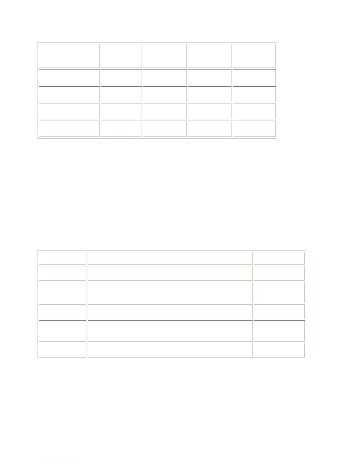
The figures on the following page show the front and rear components of the W Series 2300
system.
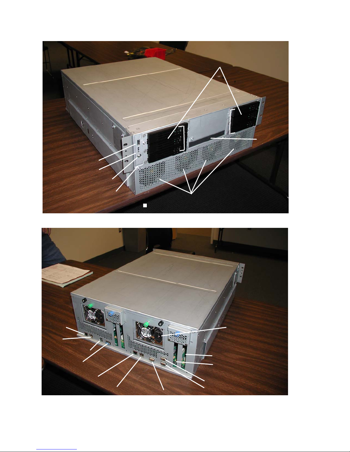
Disk Drives
Cooling Fans
Dump Button
Power Button
USB Port 3
CD-ROM
Drive
LEDs
PCI Slot 1
PCI Slot 2
Serial Port 1
Serial Port 2
Serial Port 3
Gbit Enet Port
10/100 Enet Port
USB Ports 1 & 2
Gbit Enet
Port
10/100 Enet
Port
FRONT VIEW
REAR VIEW

2. Operating System Requirements
The W Series 2300 system is currently supported by the following operating systems:
•Microsoft Windows Server 2003 Standard Edition
•ftServer System Software (ftSSS) Release 3.1 (minimum)
3. Hardware Components
The main hardware components in the W Series 2300 system are the following:
•Main motherboard
•2 SATA backplane boards
•Common IDE board
•LED board
3.1 Motherboard
The system motherboard is located at the base of the chassis. It is separated from the disks/power
supplies by a removable partition. The motherboard contains two CPU Elements and two I/O
Elements.
3.1.1 CPU Element
Each CPU element contains:
•1 processor
•4 DIMM slots
The following table lists the memory modules currently supported in W Series 2300 systems.
The table on the following page lists the possible memory configurations.
Model Number Description Minimum # per
CPU Enclosure
Maximum # per
CPU Enclosure
M228 512-MB DDR DIMM 2 4
M229 1-GB DDR DIMM 2 4
Total Memory
in Each Element
Slot 1 Slot 2 Slot 3 Slot 4
1 GB M228 DIMM M228 DIMM
2 GB M228 DIMM M228 DIMM M228 DIMM M228 DIMM
2 GB M229 DIMM M229 DIMM
4 GB M229 DIMM M229 DIMM M229 DIMM M229 DIMM
3.1.2 I/O Element
Each I/O element contains an embedded four-channel SATA controller supporting up to 3 SATA
disks. Channels 0-2 are connected to the SATA backplane and channel 3 is terminated (not
used).
Each I/O element also contains two user PCI slots (64bit/33MHz) and a dedicated VTM slot.
3.1.2.1 PCI Adapters
The W Series 2300 has two user configurable slots per I/O element.
The following table describes the specific adapters that can be configured in W Series 2300
systems. The table also includes the minimum and maximum number of adapters supported.
Model Description Min/Max No.
U574-LC 2-port Pro/1000BaseSx Fiber Ethernet PCI adapter 0/4
U574-LC-SC 2-port Pro/1000BaseSx Fiber Ethernet PCI adapter with LC-
to-SC conversion kit 0/4
U575 2-port Pro/1000Base-T Copper Ethernet PCI adapter 0/4
AK415 EMC SAN Attach Kit – (Contains 2 U525 Optical Fibre
Channel adapters) 0/2
U320-P Ultra320 PCI adapter for tape drives 0/2

3.1.2.2 PCI Slot Assignments
For consistency of manufacturing, the default is to configure adapters in the order shown in the
following table unless otherwise specified within special instructions.
Adapter PCI Slot 1 PCI Slot 2
U527 O R
U525 R O
U574 R O
U575 R O
Key:
O The corresponding PCI adapter has the option to be installed in this slot
R The corresponding PCI adapter is recommended to be installed in this slot
3.2 SATA Backplane Board
3.2.1 Disk Drives
The W Series 2300 system contains two SATA backplane assemblies, one per I/O element. Each
backplane can hold up to three SATA compliant drives.
A minimum of two internal disk drives is required. Disk drives are mirrored to the
corresponding drive bay of the partner IO element.
The following table lists the disk drive supported in W Series 2300 systems.
Model Description
D641 80-GB, 3.5”, 7200 RPM, SATA Disk Drive
D642 160-GB, 3.5”, 7200 RPM, SATA Disk Drive
The boot disk should be the smallest size available. It is required that the boot disk be installed in
the topmost drive bay (SATA channel 0).
The following table lists the internal disks and corresponding SATA-IDs.
SATA Channel 0 DISK 0 (DXXX)
SATA Channel 1 DISK 1 (DXXX)
SATA Channel 2 DISK 2 (DXXX)

When configuring mirrored internal disk drives, refer to the SATA channel numbers for the
drives shown next to the disk drives in the table.
3.3 Common IDE Board
The IDE board supports the CDROM or DVD/CDROM drive. It’s connected to the motherboard
via a 40-pin flat ribbon cable.
3.4 Front Panel (LED) Board
The Front Panel board contains the status LEDs, power button, dump button (recessed) and one
USB 1.1 Port. It’s connected to the motherboard via a 1X14-pin flat ribbon cable.
3.5 ASN Serial Modem
The C719, a 56K Data/Fax MultiTech ZBA modem, is the external serial modem used for the
Stratus Service Network (ASN). The C719 plugs into COMM 1 (COMM2 if no VTM is
installed).
3.6 Optical Devices
The CD-ROM used with the W Series 2300 can be either of the optical devices listed in the
following table.
Mktg ID Description
D551 Slimline CD-ROM drive
D552 Rewriteable optical device
3.7 EMC Attach Kits
The W Series 2300 system supports an external connection to an EMC Symmetrix/Clarrion
enclosure using a pair of U525 Fibre Channel PCI adapters contained in the AK415 Attach kit
3.8 Tape Drives
The W Series 2300 system supports the four external tape drives listed in the following table.
The tapes are connected to the U527 SCSI Adapter.
Mktg ID Description
T511 DDS-4 DAT tape drive
T521 SDLT600 (rack mount only)
T522 SDLT600 (rack mount only)

3.9 Monitor, Keyboard, Mouse, and KVM
The following table lists the monitor, keyboard, mouse, and KVM components supported on the
W Series 2300 system.
Mktg ID Description
V115 USB keyboard/mouse
N/A Customer supplied monitor
V128 Integrated rack mount KVM
V129 15” flat panel display (replaces V122)
AK470 4-Port USB KVM switch
3.10 External USB Floppy Disk Drive
An AK438 USB Floppy Disk Drive is an option for the W Series 2300. This device connects to a
W Series 2300 USB Port.
3.11 Advanced ASN Attach Kit
An optional Sentinel RMP module provides added availability features to diagnose a system
without power to the system, and the ability to power-cycle a system remotely; as well as
additional system management features of Remote KVM, Remote CD/Floppy and access to the
Stratus Service Network (ASN). The kit contains two RMP cards and requires an external
modem.
3.12 Power Distribution Units (PDUs)
An optional power configuration for rack systems is internal power jumper cables connected to a
pair of PDUs, mounted in the bottom or middle of the cabinet, which in turn is connected to AC
inlets by external PDU power cords.
The W Series 2300 system can contain a maximum of two pairs of PDUs.

4. System Configuration
Marketing ID P3401R-1D
Chassis Rack Mount
Processor DMR
SMP 1-way
Processor speed 3.06 GHz
Cache size 512 KB
Front Side Bus Speed 533 MHz
No. CPU Elements 2
No. Physical Processors 2
No. DIMM Slots 8 (4 per CPU element)
No. I/O Elements 2
No. PCI Slots 4
No. Internal Disk Drives 6 maximum

5. System Specifications
5.1 Rack-Mount System
Power
Output wattage A-side: 420W (AC)
B-side: 420W (AC)
Nominal input voltage 100-240 VAC +/- 10%; 50/60 Hz
Physical Dimensions
Height 6.5 in. (16.51 cm; 4U)
Width 17.75 in. (45 cm)
Depth 24 in. (60.96 cm)
System weight 63.9 lb. (29 kg)
Environmental
Operating temperature 41° F to 95° F (5° C to 35° C)
For every 800 ft (243.8 m) above 2000 ft (609.6 m),
lower the maximum operating temperature (35°C) by
1°C.
Maximum rate of temperature change during
operation
18° F/hr (10° C/hr) or 0.30° F/min (0.17° C/min)
Relative humidity during operation 20% to 80% (noncondensing)
Relative humidity during storage 8% to 80%
Heat dissipation 3500 BTUs per hour

5.2 Pedestal System
Power
Output wattage A-side: 420W (AC)
B-side: 420W (AC)
Nominal input voltage 100-240 VAC +/- 10%; 50/60 Hz
Physical Dimensions
Height 23.25 in. (59.05 cm.)
Width 8.62 in. (21.89 cm); 12.88 in. (32.72 cm) with skirt
Depth 31.38 in. (79.71 cm)
System weight 63.9 lb. (29 kg)
Environmental
Operating temperature 41° F to 95° F (5° C to 35° C)
For every 800 ft (243.8 m) above 2000 ft (609.6 m),
lower the maximum operating temperature (35°C) by
1°C.
Storage temperature -38° F to 140° F (-40° C to 60° C)
Operating altitude 0 ft to 10,000 ft (0m to 3,048m)
Maximum rate of temperature change during
operation
18° F/hr (10° C/hr) or 0.30° F/min (0.17° C/min)
Relative humidity during operation 20% to 80% (noncondensing)
Relative humidity during storage 8% to 80%
Heat dissipation 3500 BTUs per hour
This manual suits for next models
1
Table of contents
Other Stratus Server manuals

Stratus
Stratus ftServer 2600 Instruction Manual

Stratus
Stratus ftServer 2600 Technical manual

Stratus
Stratus ftServer 3000 Series Technical manual

Stratus
Stratus V 6624 Manual

Stratus
Stratus ftServer 2510 Technical manual

Stratus
Stratus ftServer V 2302 Technical manual

Stratus
Stratus ftserver 3300 Technical manual

Stratus
Stratus AA-E99100 Instruction Manual

Stratus
Stratus ftServer 2500 Technical manual

Stratus
Stratus ftServer V 2302 Manual


