
Salus RT520RF User manual

RT520RF THERMOSTAT - FULL USER MANUAL

TABLE OF CONTENTS
1. Introduction...............................................................................................................................................................4
1.1 Product Compliance ......................................................................................................................................................................4
1.2 Safety Informations.......................................................................................................................................................................4
2. Product Overview .......................................................................................................................................................5
2.1 Example of boilers compatible with the OpenTherm OT+ 4.0 protocol..........................................................................................6
2.2 Montage........................................................................................................................................................................................7
2.3 Package content............................................................................................................................................................................7
2.4 Proper thermostat location ...........................................................................................................................................................7
3. RXRT520 receiver ........................................................................................................................................................8
3.1 Receiver’s switches description......................................................................................................................................................8
3.2 LED indications in the receiver.......................................................................................................................................................9
3.3Wall mounting of the receiver .....................................................................................................................................................10
3.4 Connection description................................................................................................................................................................11
I A - Boiler connection ........................................................................................................................................................11
I B - Pump /Valve connection.............................................................................................................................................11
4. Before you start (rst power up) ................................................................................................................................12
4.1 LCD icon description ....................................................................................................................................................................12
4.2 Button description.......................................................................................................................................................................12
4.3 First power up sequence and conguration.................................................................................................................................13
4.4 OpenTherm - HotWater conguration.........................................................................................................................................17
4.5 Max boiler temperature settings.................................................................................................................................................17
5. User settings ............................................................................................................................................................18
5.1 Manual mode..............................................................................................................................................................................18
5.2 Schedule mode - programming schedule....................................................................................................................................19
5.3 Switching between manual and schedule mode.........................................................................................................................20
5.4 BOOST mode - hourly temperature override (+Hr)......................................................................................................................21
5.5 Control and Heat/Cool settings....................................................................................................................................................22
5.6 OFFSET temperature calibration..................................................................................................................................................23
5.7 Landlord settings ........................................................................................................................................................................24
5.8Time/Date ...................................................................................................................................................................................26
5.9 Holiday mode..............................................................................................................................................................................27
5.10 Language ..................................................................................................................................................................................28
6. RT520RF thermostat pairing with the receiver............................................................................................................29
7. Test the pairing process.............................................................................................................................................30
8. Factory Reset............................................................................................................................................................31
9. Error codes ...............................................................................................................................................................31
10. Battery change .......................................................................................................................................................31
11. Cleaning and Maintenance ......................................................................................................................................32
12. Technical Informations ............................................................................................................................................32
13. Warranty ................................................................................................................................................................33


4
This product complies with the essential requirements and other relevant provisions of Directives 2014/53/EU and 2011/65/EU. The full text of the EU
Declaration of Conformity is available at the following internet address: www.saluslegal.com.
• Before starting installation work and before using the product, read the entire manual.
•The information contained in the instructions is essential for proper functioning.
•To avoid accidents resulting in personal injury and material damage, please follow all safety precautions, specied in this manual.
• The device should not be used by people with limited mental, sensory or mental abilities, without experience, of insucient knowledge as well as
children.
• Do not use an unassembled device (eg without a cover).
•The device may only be opened by a qualied person.
• Keep electrical devices out of the reach of children and ensure that they do not play with it. Children should not be left unattended. If necessary,
disconnect the control system for the entire room.
• Do not leave the packaging, cabinet, or any loose parts of the device unattended, as they pose a risk to children.
WARNING!
• Installation must be carried out by a qualied person with appropriate electrical qualications in accordance with standards and regulations in force in
the given country and in the EU.
• Never try to connect the device other than as described in the manual.
• Before assembly, repair or maintenance as well as during any connection works it is absolutely necessary disconnect the mains supply and make sure
that the terminals and electric wires are not live.
•The device may not be exposed to extreme temperatures, strong vibrations or subjected to mechanical shock.
• The device should not be used in unfavorable environmental conditions or in rooms where there is a concentration of ammable gases, fumes or dust.
WARNING!
•There may be additional protection requirements for the entire installation that the installer is responsible for maintaining.
1. Introduction
1.1 Product Compliance
1.2 Safety Informations
Care for the natural environment is of paramount importance to us.The awareness that we manufacture electronic devices obliges us
to dispose of used electronic components and devices safely.Therefore the company has received a registration number issued by the
ChiefInspector for Environmental Protection.The crossedoutsymbol the trashcan on the product means thatthe product must not be
disposed of with ordinary waste containers. Sorting waste for recycling helps to protect the environment. It is the user’s responsibility
to surrender used equipment to a designated collection point for recycling waste from electrical and electronic equipment.

5
The RT520RF room thermostat simply switches the heating system on and o as necessary. It works by sensing the air temperature, switching on the
heating when the air temperature falls below the thermostat setting, and switching it o once this set temperature has been reached.
Turning a room thermostat to a higher setting will not make the room heat up any faster. How quickly the room heats up depends on the design of the
heating system, for example, the size of boiler and radiators. Neither does the setting aect how quickly the room cools down.Turning a room thermostat
to a lower setting will result in the room being controlled at a lower temperature, and saves energy.
The heating system will not work if a time switch or programmer has switched it o.
The way to set and use your room thermostat is to nd the lowest temperature setting that you are comfortable with, and then leave it alone to do its
job. The best way to do this is to set the room thermostat to a low temperature – say 18⁰C – and then turn it up by one degree each day until you are
comfortable with the temperature.
You won’t have to adjust the thermostat further. Any adjustment above this setting will waste energy and cost you more money.
If your heating system is a boiler with radiators, there will usually be only one room thermostat to control the whole house. But you can have dierent
temperatures in individual rooms by installing thermostatic radiator valves (TRVs) on individual radiators. If you don’t have TRVs, you should choose a
temperature that is reasonable for the whole house. If you do haveTRVs, you can choose a slightly higher setting to make sure that even the coldest room
is comfortable, then prevent any overheating in other rooms by adjusting theTRVs.
Room thermostats need a free ow of air to sense the temperature, so they must not be covered by curtains or blocked by furniture. Nearby electric res,
televisions, wall or table lamps may prevent the thermostat from working properly.
Thermostat is compatibile with OpenTherm OT+ 4.0 version.
The OpenTherm protocol is an open standard communication protocol used in central heating systems for two-way communication between a central
heating boiler and a room thermostat.Thanks to the communication protocol, the boiler power is modulated, which can signicantly increase the energy
eciency of the heating system while maintaining the set temperature in the room. OpenTherm modulation, compared to standard communication (ON
/ OFF), occurs by setting the desired temperature of water from the boiler (boiler power), and not by its cyclical switching on and o.
PLEASE NOTE!
Make sure your gas combi boiler is compatible with OT + 4.0 communication protocol.
The list of compatible boilers is on the next page.
Product advantages:
• set is factory-paired and ready to work
• option to choose Hysteresis or built-inTPI algorithm for all types of heating
• works with time schedules
• service mode protected by a PIN code
• maximum / minimum temperature limitation
• can temporarily change the temperature (overwriting until the next program change)
• has unique transmission codes
• operates at 868 MHz - a stable and noise-resistant signal
2. Product Overview

6
COMPANY MODEL
Alpha Heating
E-Tec S
E-tec Plus
E-tec
Evoke
Intec GS
Atag
iC
iC Economiser
iS
Baxi
100 Combi
200 Combi
400 Combi
600 Combi
Daikin
D2CND 24Kw
D2CND 28kw
D2CND 35kw
Ferroli i25 Condensing Combination Boiler
i29 Condensing Combination Boiler
Ideal
Independent + Combi
Independent Combi
Independent System
Logic Combi+ Combi C
Logic Combi C24, C30, C35 (via a separate bundle set)
Logic Code Combi (via a separate bundle set)
I-mini C24, c30 (via a separate bundle set)
Vogue Combi C26,C32, C40
Logic + System
Logic + Heat
Intergas
Intergas Rapid
Intergas Rapid Plus
Combi Compact, Compact Range
ECO RF
Xtreme
Xclusive
Main Eco Compact Combi 25-30
Navien Navien NCB
Ravenheat
Avanta, Quinta Ace
Quinta Pro
Gas 110 Eco
Vokera
Evolve C
Evolve S
Linea One (przez OpenTherm Kit Part_1221179)
Vision Combi (requires a control interface 294501430
Compact A (requires a control interface 29450143)
Verve (only heating mode)
Mynute I (only heating mode)
Vision System (only heating mode)
Unica I
Vibe
Vision C
COMPANY MODEL
Vokera
Linea HE
Mynute A
Mynute HE
Unica HE
Viessmann
Vitodens 100WTyp WB1A (Connection: X3.3 and X3.4)
Vitodens 100W Typ WB1B (Connection: X21.1 and
X21.2)
Vitodens100WTypWB1C(Connection:X21.1 andX21.2)
Vitodens 200-W WB2B 26+ 35 kW (via Expansion Mo-
dule OT and OT-A8 + _Terminal -10 and +10 are on the
extension of the A8 boiler)
Vitodens 200-W WB2C, B2HA,B2JA, B2LA (via icm
Expander OpenTherm)
Vaillant
(viaVaillant
VR33 module)
Ecotec Pro
Ecotec Plus
Ecotec Exclusive
Ecot Pure
Worcester
Bosch
(via Net
EMS-OT
OpenTherm
converter)
EMS capable boilers
Greenstar i
Greenstar i Junior (Made in July 2013)
Greenstar Si Compact
Greenstar CDi Compact
Greenstar CDi Classic (Made after 16.01.2007 with
CF12.10 software version and newer)
Greenstar Highow CDi
Greenstar 12i System – 24i System (On condition that
an optional integrated diverter valve manufactured
after February 2011 is installed)
Greenstar 27i System – 30i System (Provided the optio-
nal Integrated Changeover Valve is installed Greenstar
CDi Classic System (provided the optional Integrated
Changeover Valve manufactured after 02/16/2007 with
software version CF12.10 and above is installed))
2.1 Example of boilers compatible with the OpenTherm OT+ 4.0 protocol

7
2.2 Montage
2.3 Package content
1) RT520RF thermostat
2)Thermostat bracket
3) RXRT520 receiver
4) 2x AA batteries
5) Short instruction
6) Mounting screws
2.4 Proper thermostat location
Please note:
The ideal position to thermostat mounting is about 1,5m under oor level far from heating or cooling sources. Thermostat can’t be
exposed to sunlight or any extreme conditions like for example draft.
Because of re and explosion risk there is not allowed to use thermostat in atmosphere of explosive gases and ammable liquids (eg coal dust). In case
if any of listed dangers occur you have to use additional protection measures – anti-dust and explosive gases (tight cover) or prevent their formation.
Furthermore, thermostat can’t be used in condensation of water vapor conditions and be exposed to water action.
1
4
2 3
56

8
3. RXRT520 receiver
3.1 Receiver’s switches description
The thermostat communicates wirelessly with the RXRT520 receiver. The receiver should be supplied with 230VAC, the maximum load of the receiver is
16A. Avoid installing the device in places directly exposed to water, moisture and air condensation. The RXRT520 receiver can operate in two dierent
modes - AUTO (automatic) and MANUAL (manual).To select a specic mode, use the buttons on the front of the receiver.
For the receiver to work with the thermostat, set the switches to the ON / AUTO position.
2.
4.
3.
1.
TOP SWITCH
1. ON - Manual mode - receiver ON
2. OFF - Manual mode - receiver OFF
BOTTOM SWITCH
3. AUTO - Receiver works in AUTO mode (according to
the thermostat’s command)
4. MANUAL - Receiver works in manual mode
(according to the top switch)
REMEMBER!:

9
The status of the RXRT520 receiver is indicated by two LEDs.These are
LEDs with the following colors:
- red (upper one),
- green (lower one).
A detailed explanation of the meaning of the LEDs can be found in the table below:
MEANING
The red LED lights up
The receiver is connected to the 230V power supply and is paired with the thermostat.
The receiver can be thermostat-enabled if it is in automatic mode when the lower switch is in the AUTO position.
The receiver can be started manually when the lower switch is in the MANUAL position.
The red LED ashes
The receiver is in the pairing mode and is looking for a signal from the thermostat (then you must activate the
“PAIRING”option in the thermostat)
(or)
The receiver was paired but lost communication with the thermostat due to out of range or low battery in the
thermostat. The receiver starts ashing after one hour of time when it does not receive a signal from the thermostat.
The red diode is o The receiver is disconnected from the 230V power supply or the upper switch is in the OFF position.
The green diode lights up
In automatic mode, the receiver received a heating signal from the thermostat.
The receiver was started in manual mode (upper ON switch, lower MANUAL switch)
The green diode is o The receiver does not send a heating signal.
3.2 LED indications in the receiver
1
2
1
2
10
3.3 Wall mounting of the receiver
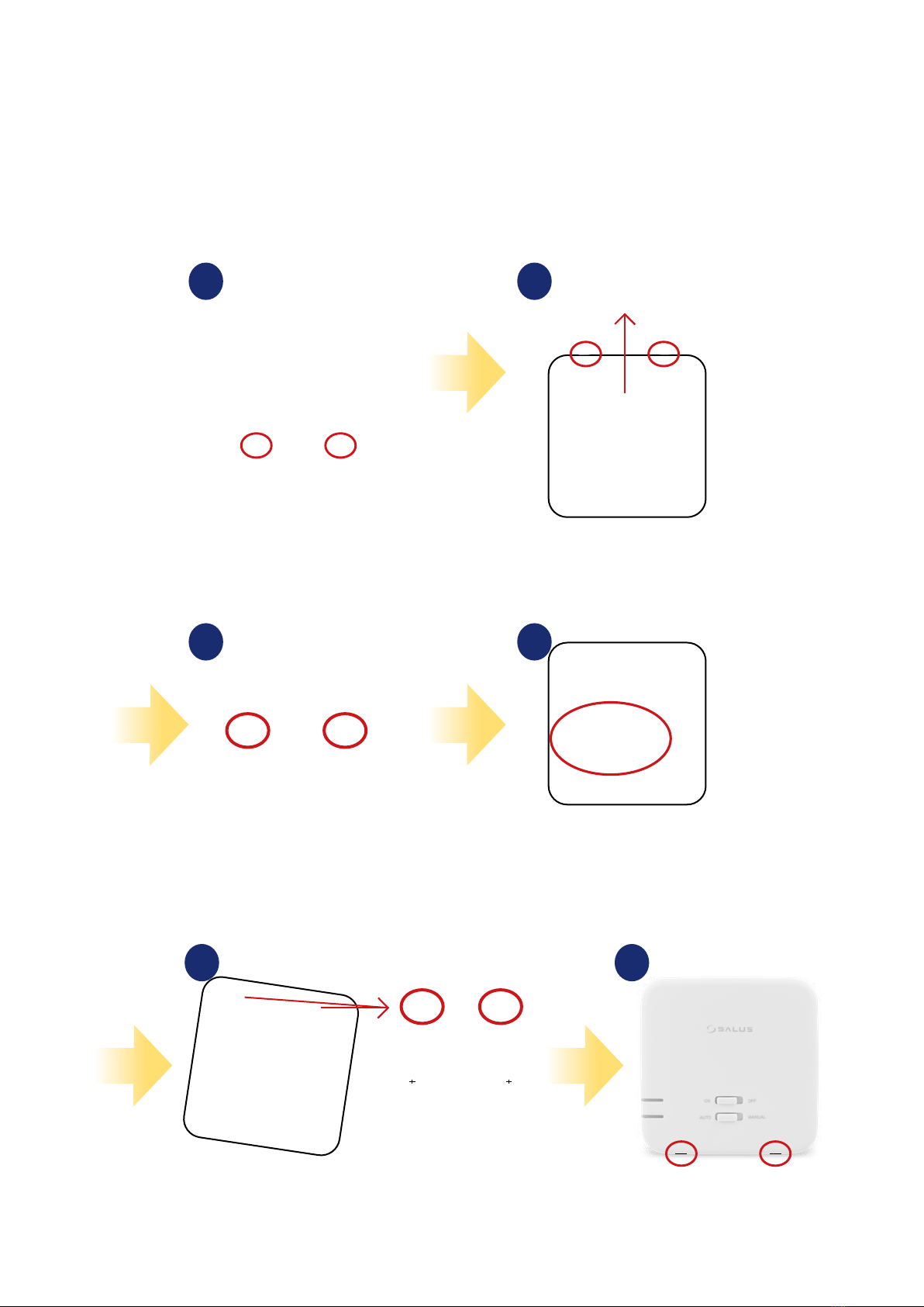
Wall mounting the receiver: drill two ø6 mm holes in the wall. Insert the plugs and, by putting the plate to the wall (included in the set), put the two
screws through the holes and then screw them in. Connect the necessary cables to the receiver. Next, hang the receiver on the board using the handles
designed in the receiver, marked in the picture below.
Loosen the screws with a scre-
wdriver just enough to tilt the
back housing.
Attach the back housing to the wall
(keeping the correct positioning of the
plastic„hinges”) using the marked holes
(see the picture above).
Put the receiver from above on the back
housing attached to the wall, according to
the position of the plastic„hinges”.
Tighten the screws from the
bottom of the back housing.
Tilt the receiver cover upwards
(according to the position of the
„hinge”).
Then, correctly connect the wires
included in the set with the
receiver (see„connection diagrams”
on page 11).
1
3
5 6
2
4
3
....
This manual suits for next models
1
Table of contents
Other Salus Thermostat manuals

Salus
Salus VS20WRF User manual

Salus
Salus HTRS230 User guide

Salus
Salus RT310TX User manual

Salus
Salus WBRT520TX User manual

Salus
Salus RT510WBC User manual

Salus
Salus ST620VBC User manual

Salus
Salus ST325TX User manual

Salus
Salus WBNTSQ61024 Quantum User manual

Salus
Salus ERT30 User manual

Salus
Salus RT510 User manual


Popular Thermostat manuals by other brands


Saswell
Saswell SAS920XWHB-7-S-RF User manual and warranty card

Aircalo
Aircalo TFP1-ET85P2 operating manual

Honeywell
Honeywell CM721 user manual

Carrier
Carrier DEBONAIR 33CS Installation and operating instructions

Lennox
Lennox iHarmony Zone Thermostat Installation and setup guide

Gemtech
Gemtech GT7000 Operation


