RFM HN 291D/X User manual

HN 291D/X – HN294D/X
RS-232 Serial Modbus Radio
User’s Guide

Important Regulatory Information
Cirronet Product FCC ID: HSW-910M
IC 4492A-910M
Note: This unit has been tested and found to comply with the limits for a Class A digital device, pursuant
to part 15 of the FCC Rules. These limits are designed to provide reasonable protection against harmful
interference when the equipment is operated in a commercial environment. This equipment generates,
uses, and can radiate radio frequency energy and, if not installed and used in accordance with the
instruction manual, may cause harmful interference to radio communications. Operation of this equipment
in a residential area is likely to cause harmful interference in which case the user will be required to correct
the interference at their expense.
FCC s MPE Requirements
Information to user/installer regarding FCC s Maximum Permissible Exposure (MPE) limits.
Notice to users/installers using the 8.5 dBi Yagi antenna with the WIT910.
FCC rules limit the use of this antenna, when connected to the WIT910 module, to point-to-point
applications only. It is the responsibility of the installer to ensure that the system is prohibited
from being used in point-to-multipoint applications, omni-directional applications, and
applications where there are multiple co-located intentional radiators transmitting the same
information. Any other mode of operation using this antenna is forbidden.
Notice to WIT910 users/installers using the following fixed antennas:
Cushcraft 8.5 dBi Yagi
The field strength radiated by this antenna, when connected to a transmitting WIT910, may
exceed FCC mandated RF exposure limits. FCC rules require professional installation of these
antennas in such a way that the general public will not be closer than 23 cm from the radiating
aperture of this antenna. End users of these systems must also be informed that RF exposure
limits may be exceeded if personnel come closer than 23 cm to the aperture of this antenna.
Notice to WIT910 users/installers using the following fixed antennas:
Cushcraft 6 dBi Monopole Cushcraft 3 dBi Omni Ace 2dBi dipole
The field strength radiated by any one of these antennas, when connected to a transmitting
WIT910, may not exceed FCC mandated RF exposure limits. FCC rules require professional
installation of these antennas in such a way that the general public will not be closer than 20 cm
from the radiating aperture of any of these antennas. End users of these systems must also be
informed that RF exposure limits may be exceeded if personnel come closer than 20 cm to the
apertures of any of these antennas.
Changes or modifications not expressly approved by the party responsible may void the users ability to
operate the equipment.

Table of Contents
Introduction .................................................................................................................. 1
HopNet Benefits........................................................................................................... 1
Operating Frequency ............................................................................................... 1
HopNet Frequency Hopping Spread Spectrum Advantages....................................1
HopNet Data Integrity............................................................................................... 2
Flexible Power Management....................................................................................2
Advanced Features...................................................................................................... 2
The HopNet Family of Products ...................................................................................3
Accessories..............................................................................................................3
Getting Started................................................................................................................4
Install the HopNet Configuration Wizard on a PC. .......................................................4
Connect the HopNet radio to the PC............................................................................4
Set one HopNet radio to act as the Base..................................................................... 5
Run a communications test..........................................................................................7
The Serial Adapter Box................................................................................................8
3 Wire Operation...................................................................................................... 8
Remote Pin-Out, RS-232......................................................................................... 9
Guidelines for Installation........................................................................................... 10
Aiming the Antenna and Placing the Remote.............................................................10
Interconnect Cable..................................................................................................... 10
Configuring the Network................................................................................................ 11
HopNet Configuration Wizard (5.0 or later)................................................................ 11
About the INIT.INI File................................................................................................ 13
Parameters Tab ..................................................................................................... 14
RF Tools ................................................................................................................ 23
WinCom Window.................................................................................................... 27
Function Keys ........................................................................................................ 30
Recover.................................................................................................................. 30
Restart ...................................................................................................................31
Saving Configurations................................................................................................ 31
Modbus Operation...................................................................................................... 31
Automatic Addressing............................................................................................ 32
Serial Commands....................................................................................................... 33
Network Commands................................................................................................... 34
Status Commands...................................................................................................... 39
Memory Commands...................................................................................................40
Modbus Adapter Commands...................................................................................... 41
Modem Command Summary ..................................................................................... 42
Troubleshooting ............................................................................................................43
Overview.................................................................................................................... 43
Introduction ............................................................................................................43
Transceiver Requirements.....................................................................................43
Common System Problems........................................................................................ 44
Guidelines for Reducing Interference.........................................................................45
Introduction ............................................................................................................45

Guidelines for Setting Up the Network................................................................... 45
Guidelines for Selecting Your Site.......................................................................... 45
Guidelines for Avoiding Terrain Obstructions............................................................. 46
Customer Support...................................................................................................... 47
Introduction ............................................................................................................47
Technical Assistance ............................................................................................. 47
Factory Repairs...................................................................................................... 47
Technical Specifications................................................................................................48
Electrical ................................................................................................................48
Mechanical............................................................................................................. 49
Environmental........................................................................................................ 49
Glossary of Terms......................................................................................................... 50
Warranty........................................................................................................................ 52

HN-291D
Introduction
The HopNet 910 family of products provides reliable wireless connectivity for either
point-to-point or point-to-multipoint applications. HN-91 products are built around
the WIT910 radio transceiver, which employs frequency hopping spread spectrum
technology. This technology ensures:
•Maximum resistance to noise
•Maximum resistance to multipath fading
•Robustness in the presence of interfering signals
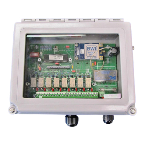
The HN-291D and HN-291DX consist of a DIN-rail mount serial adapter and a
NEMA4X (IP66) rated radio assembly. The HN-291D has an integral 3dB patch
antenna while the HN-291DX has an external antenna connector. The radio assembly
connects to the serial adapter through an integrated 50-foot cable. The HN-294D and
HN-294DX are the same as the HN-291D and HN-291DX with a 4 foot cable on the
radio assembly. The HopNet D and DX versions can act as either Bases or Remotes.
The HN-291D has an internally mounted 3 dBi patch antenna. The built-in antenna
greatly eases outdoor installation since no antenna feedline cable or adapters are
needed. The 3 dBi antenna gain increases the radiated EIRP to +30 dBm and the
effective receiver sensitivity to –106 dBm. The HopNet DX has a TNC connector for
attaching an antenna.
HopNet Benefits
All HopNet 910 products work with each other and can be mixed and matched in a
single network. All HopNet 910 products are WIT910 compatible and can be used
with WIT910 OEM based products as well as with the SNAP910 10/100BaseT serial-
to-Ethernet access point.
Operating Frequency
The HopNet 910 family operates in the 900 MHz ISM band that allows for license-
free use in the Americas and Australia.
HopNet Frequency Hopping Spread Spectrum Advantages
In the frequency domain, a multipath fade can be described as a frequency selective
notch that shifts in location and depth over time. Multipath fades typically occupy
five percent of the band. A conventional radio system typically has a five percent
chance of signal impairment at any given time due to multipath fading.
Frequency Hopping Spread Spectrum reduces the vulnerability of a radio system to
interference from jammers and multipath fading by distributing or spreading the
signal over a larger region of the frequency band.
The fade resistant, HopNet frequency-hopping technology employs up to 54 channels
and switches channels over 30 times a second to achieve high reliability throughput.
©2000- 2004 Cirronet™Inc 1 M-0910-0002 Rev B

HN-291D
HopNet Data Integrity
An on-board 512 byte buffer and error correcting over-the-air protocol ensure data
integrity even in the presence of weak signals or jammers. The serial interface
handles both data and control of asynchronous data rates of up to 115 Kbps.
Flexible Power Management
The power can be set at 10 mW, 100 mW or 500mW using the included software.
Reduced power can reduce the size of the coverage zone, which may be desirable for
multiple network indoor applications. You can also place the transceiver module in a
power-save mode, which enables smart power management. Smart power
management allows a remote unit to drop into a lower current standby mode during
transmission or receiving gaps. This feature also allows HopNet products to be used
in various countries where the output power requirements may vary due to regulation.
Advanced Features
HopNet modems have many advanced features:
•Employ frequency hopping technology with up to 54 channels in the 900MHz
frequency range
•Support digital addressing for up to 32 networks, with 62 remotes per
network.
•Point-to-point and point-to-multipoint operation
•Use transparent ARQ protocol
•Use same hardware for all supported data rates
•Supports up to 115 Kbps asynchronous data rates
•Full Duplex operation
•Store setup configuration in nonvolatile memory (FLASH)
•Fast acquisition – less than 4 seconds is the typical time to acquire hopping
pattern
•Modbus mode with automatic addressing
©2000- 2004 Cirronet™Inc 2 M-0910-0002 Rev B

HN-291D
The HopNet Family of Products
The HopNet 910 family consists of the following products:
HN-291
HN-291X
HN-291D
HN-294
HN-294X
HN-291DX
HN-294D
HN-294DX
HN-591
SNAP910
SNAP910X
SNAP910D
SNAP910DX
Accessories
Antennas
2dB Omnidirectional
5dB Omnidirectional
6dB Yagi
9dB Yagi
Replacement Serial Adapter
Replacement Power Supply
©2000- 2004 Cirronet™Inc 3 M-0910-0002 Rev B

HN-291D
Getting Started
A pair of HopNet radios are set up by performing the following steps:
•Install the HopNet Wizard configuration program on a PC
•For X version radios, attach external antenna
•Connect the HopNet radio to the PC
•Set one HopNet radio as a base radio
•Run a communications test
These steps are described in detail below. Other steps you may want to perform
include:
•Change the baud rate
•Change the radio network number
•Change how fast the radios change frequencies
Refer to the Configuring the Network section of this manual for details on these steps.
Install the HopNet Configuration Wizard on a PC.
The HopNet Configuration Wizard is located on the software and documentation CD
included in the HopNet radio package. Install the program by inserting the CD in the
PC and following the installation wizard. If autorun has been turned off, double-click
on setup.exe on the CD to start the wizard.
Connect the HopNet radio to the PC.
Plug one end of the serial cable provided to a serial port on the PC…
©2000- 2004 Cirronet™Inc 4 M-0910-0002 Rev B

HN-291D
…and the other end of the serial cable to the DIN rail serial adapter box.
Connect the end of the cable (RJ-45 connector) from the HopNet radio to the DIN rail
serial adapter box.
NOTE: Make sure the RUN/CONFIG switch is in the CONFIG position.
Connect power to the HopNet radio by plugging one end of the wall-mount power
supply into the serial adapter box and the other end into a wall outlet. A green LED
on the serial adapter box will turn on indicating power is present.
Set one HopNet radio to act as the Base.
When using HopNet radio, one unit, and only one, must be set as the Base. All other
HopNet radios must be set as Remotes. With a HopNet radio connected to the PC,
start the HopNet Configuration Wizard program by double-clicking on the icon on the
desktop. The HopNet Configuration Wizard will automatically detect which serial
port the HopNet radio is connected to and its baud rate. When the radio has been
detected, the Continue button will appear.
Click on the Continue button to bring up the next screen.
©2000- 2004 Cirronet™Inc 5 M-0910-0002 Rev B

HN-291D
The program will read and display the current settings of the HopNet radio. The
HopNet radio is shipped from the factory as a Remote. The Remote button on the
Wizard screen will appear depressed indicating the HopNet radio is a remote.
NOTE: The S/N displayed in the bottom left corner is the serial number of the
radio inside the unit and is different from the serial number of the HopNet unit.
Both the HopNet unit serial number and the radio serial number are on the radio
unit of the HopNet product.
To set the HopNet radio as a base, click on the Base button. The Base button will
depress and the Remote button will pop up. The screen heading will change from
“Remote Parameters” to “Base Parameters.”
©2000- 2004 Cirronet™Inc 6 M-0910-0002 Rev B
This manual suits for next models
1
Table of contents