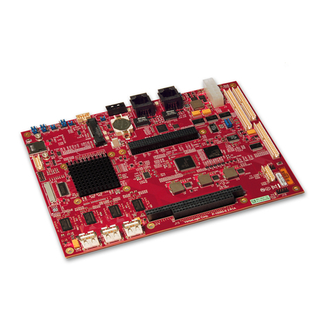
Portwell ROBO-679 User manual

ROBO-679
Single Board Computer
User′s Manual
P/N : 861106790047 Version 1.0
Copyright © Portwell, Inc., 1999. All rights reserved.
All other brand names are registered trademarks of their respective owners.
StockCheck.com

EC Declaration of Conformity
(To Be Added)
For the following equipment :
Product Name :
Model Name :
Trade Name :
is herewith confirmed to comply with the requirements set out in the Council
Directive on the Approximation of the Laws of the Member States relating to
Electromagnetic Compatibility Directive (89/336/EEC). The equipment was
evaluated and passed the test, the following standards were applied :
EMC : EN 55022 (1994/A1:1995 Class A)
EN 50082-2 (1995)
EN 61000-4-2 (1995)
EN 61000-4-3 (1996)
EN 61000-4-4 (1995)
The following manufacturer is responsible for this declaration :
Portwell Inc.
(Company Name)
3F, No. 88, Sec. 1, Nei-Hu Rd., Taipei, Taiwan, R.O.C.
(Company Address)
Taipei, R.O.C. Oct. 29,1998
Place Date Legal Signature of
Authorized Person
StockCheck.com

T
Table of Contents
How to Use This Manual
Chapter 1. Introduction
1-1 Check List .............................................................................................. 1-2
1-2 Product Specifications.......................................................................... 1-3
1-3 System Architecture ............................................................................. 1-6
Chapter 2. Hardware Configuration Setting
2-1 Jumpers.................................................................................................. 2-1
2-2 Connectors............................................................................................. 2-3
Chapter 3. System Installation
3-1 Socket 370 Celeron /Pentium-III Processor ...................................... 3-1
3-2 Main Memory ....................................................................................... 3-2
3-3 M-systems Flash Disk .......................................................................... 3-3
3-4 Installing the Single Board Computer ............................................... 3-4
3-4-1 INF Chipset Component Driver............................................... 3-4
3-4-2 Intel 82815 GMCH Graphics Controller.................................. 3-5
3-4-3 Intel 82559 / 82801BA MAC Fast Ethernet Controller .......... 3-6
3-4-4 On-board 68-pin PCI connector............................................... 3-6
3-5 Clear CMOS Operation........................................................................ 3-7
3-6 Watch Dog Timer Programming........................................................ 3-7
Chapter 4. BIOS Setup Information
4-1 Entering Setup...................................................................................... 4-1
4-2 Main Menu ........................................................................................... 4-2
4-3 Standard CMOS Setup Menu............................................................. 4-3
4-4 IDE Adaptors Setup Menu................................................................. 4-4
4-5 Advanced BIOS Features.................................................................... 4-6
4-6 Advanced Chipset Features ............................................................... 4-9
4-7 Integrated Peripherals......................................................................... 4-13
4-8 Power Management Setup ................................................................. 4-18
4-9 PnP/PCI Configuration Setup........................................................... 4-22
4-10 PC Health Status.................................................................................. 4-25
4-11 Frequency/Voltage Control............................................................... 4-26
4-12 Default Menu ....................................................................................... 4-28
4-13 Supervisor/User Password Setting................................................... 4-28
4-14 Existing Selection................................................................................. 4-29
4-15 POST Messages.................................................................................... 4-30
4-16 BIOS POST Check Point List.............................................................. 4-35
4-17 BIOS Flash Utility ................................................................................ 4-40
StockCheck.com

Chapter 5. Troubleshooting
5-1 Backplane Setup................................................................................... 5 – 1
5-2 Onboard Hardware Installation .................................................... 5 – 5
5-3 BIOS Setting .................................................................................... 5 – 6
5-4 OS Diagnostics..................................................................................... 5 – 7
StockCheck.com

How to Use This Manual
The manual describes how to configure your ROBO-679 system to meet
various operating requirements. It is divided into five chapters, with each
chapter addressing a basic concept and operation of Single Board Computer.
Chapter 1 : Introduction. presents what you have in the inside of box and
give you an overview of the product specifications and basic system
architecture for this model of single board computer.
Chapter 2 : Hardware Configuration Setting. shows the definitions and
locations of Jumpers and Connectors that you can easily configure your
system.
Chapter 3 : System Installation. describes how to properly mount the CPU,
main memory and M-systems flash disk to get a safe installation and give you
a programming guide of Watch Dog Timer function.
Chapter 4 : BIOS Setup Information. specifies the meaning of each setup
parameters and how to get advanced BIOS performance and update new
BIOS. In addition, POST checkpoint list will give you a guide of
trouble-shooting.
Chapter 5 : Troubleshooting. gives you a few reminding hints in building up
a valid and working system with ROBO-679, in terms of hardware and
software perspective. Issues addressed are based on the customer application
history collected throughout the years, and are presented as the most
frequently encountered problems.
The content of this manual and EC declaration document is subject to change
without prior notice. These changes will be incorporated in new editions of
the document. Portwell may make supplement or change in the products
described in this document at any time.
Updates to this manual, technical clarification, and answers to frequently
asked questions will be shown on the following web site :
http://isc.portwell.com.tw
StockCheck.com

Introduction
ROBO-679 User’s Manual
1-1
CHAPTER 1
I
Introduction
The ROBO-679 all-in-one single board computer is designed to fit a high
performance Celeron/Pentium-III based CPU and compatible for high-end
computer system with PCI Local Bus architecture. It is made to meet
today’s demanding pace, and keep complete compatibility with hardware
and software designed for the IBM PC/AT. It is beneficial to build up a
high performance system for VARs, or system integrators. The on-board 3D
Graphics display, and fast Ethernet interface will bring full functionality and
high performance to all segments of the industrial PC market.
This single board computer runs with Intel Celeron/Pentium-III (FC-PGA &
FC-PGA2) processor, and supports DIMM up to 512 MB SDRAM. The
enhanced on-board PCI IDE interface can support 4 drives up to PIO mode 4
timing and Ultra DMA/33/66/100 synchronous mode feature. The on-
board Super I/O Chipset integrates one floppy controller, two serial ports,
one keyboard controller, one hardware monitor, one IrDA port and one
parallel port. Two high performance 16C550-compatible UARTs provide
16-byte transmit/receive FIFOs, and the multi-mode parallel port supports
SPP/EPP/ECP function. Besides, three USB (Universal Serial Bus) ports
provide high-speed data communication between peripherals and PC. PCI
type daughter board can also be compatible to ROBO-679.
The PICMG standard makes the ROBO-679 work with the legacy ISA,
ISA/PCI or multi-slots PCI-bus backplane. The on-board 32-pin DIP socket
supports M-systems DiskOnChip 2000 product up to 288MB. The Watch-
Dog Timer function can be used to monitor your system status. One 6-pin
Mini-DIN connector (with Y-Cable) is provided to connect PS/2 Mouse and
Keyboard. The on-board Flash ROM is used to make the BIOS update
easier. A standard 5-1/4” drive power connector is reserved to directly get
more power energy for big power applications, and the additional 5-pin
shrouded connector is reserved for connecting Keyboard interface on the
backplane. One 4-pin header is designed to support ATX power function.
All of these features make ROBO-679 excellent in stand-alone applications.
StockCheck.com

Introduction
ROBO-679 User’s Manual
1-2
1
1-1 Check List
The ROBO-679 package should cover the following basic items accompany with this
manual.
•One ROBO-679 single board computer
•One Parallel Port cable kit
•One Serial Port cable to support two interfaces
•One FDC cable
•One IDE cable
•One Y-Cable cable for PS/2 Keyboard and Mouse
•One 5-pin to 5-pin keyboard cable for backplane connection
•One 4-pin ATX power control cable for backplane connection
•One CD-Title ROBO-679 to supply Intel 82815 GMCH VGA display driver, Intel
82801BA ICH2 integrated LAN controller driver.
If any of these items is damaged or missing, please contact your vendor and keep all
packing materials for future replacement and maintenance.
StockCheck.com

Introduction
ROBO-679 User’s Manual
1-3
1
1-2 Product Specifications
•Main processor
Intel Celeron and Pentium-III processors
CPU bus frequency : 66/100/133 MHz
CPU core/bus clock ratio : x2 to x8
Standard socket 370 for FC-PGA/FC-PGA2 CPU (No support for PPGA370
Celeron)
•BIOS
Award system BIOS with 4Mb Firmware Hub to support DMI, PnP, APM, and
ACPI
•Main Memory
Two 168-pin DIMM sockets, supporting PC133/PC100 SDRAM up to 512MB (No
ECC and Registered DIMM Support)
•L2 Cache Memory
128KB/256KB L2 Cache built in Celeron and 256KB/512KB built in Pentium-III/
Pentium-III-S processor
•Chipset
Intel 815E B-step Chipset
•Bus Interface
Follow PICMG 1.0 Revision 2.0 standard (32-bit PCI and 16-bit ISA)
Fully complies with PCI Local Bus specification V2.1 (support 4 master PCI slots)
•PCI IDE Interface
Support two enhanced IDE ports up to four HDD devices with PIO mode 4 and
Ultra DMA/33/66/100 mode transfer and Bus Master feature
•Floppy Drive Interface
Support one FDD port up to two floppy drives and 5-1/4"(360K, 1.2MB), 3-1/2"
(720K, 1.2MB, 1.44MB, 2.88MB) diskette format and 3-mode FDD
!!!
•Serial Ports
Support two high-speed 16C550 compatible UARTs with 16-byte T/R FIFOs
!!!
•IR Interface
Support one 6-pin header for serial Standard Infrared wireless communication
!!!
StockCheck.com

Introduction
ROBO-679 User’s Manual
1-4
•Parallel Port
Support one parallel port with SPP, EPP and ECP modes
•USB Interface
Support three USB (Universal Serial Bus) ports for high speed I/O peripheral
devices
•PS/2 Mouse and Keyboard Interface
Support one 6-pin Mini-DIN connector and one 5-pin shrouded connector for
PS/2 mouse/keyboard connection through Y-Cable and backplane connection
•ATX Power Control Interface
One 4-pin header to support ATX power control with Modem Ring-On and Wake-
On-LAN function
•Auxiliary I/O Interfaces
System reset switch, external speaker, Keyboard lock and HDD active LED
•Real Time Clock/Calendar (RTC)
Support Y2K Real Time Clock/calendar with battery backup for 7-year data
retention
•Watchdog Timer
Support 255 intervals from 0.5 sec./min. to 254.5 sec./min. by software
programming
•Disk-On-Chip (DOC) Feature
Reserved one 32-pin socket for M-systems Flash Disk up to 288MB
DOS, Windows, Win95, NT (bootable) drivers and Utility supported
•On-board VGA
Intel 82815 GMCH integrated graphics controller with 4MB memory
•On-board Ethernet LAN
Intel 82801BA ICH2 integrated LAN controller to support RJ-45 interface at
10/100 Base-T speed
•On-board 68-pin PCI device connector
Support one additional PCI device daughter board
•High Driving Capability
Support 64mA high driving capability for multi-slots ISA-bus
StockCheck.com

Introduction
ROBO-679 User’s Manual
1-5
•External Power Connector
Support one standard 5-1/4” disk drive power connectors to enhance power
driving
•Power Good
On-board power good generator with reset time, 300ms 500ms
•CPU Cooling Fan
Support two 3-pin headers with wafer
•System Monitoring Feature
Monitor CPU and system temperature, operating voltage, and fan status
•Bracket
Support one Mini-DIN, one-port USB, one Ethernet port and one VGA port
•Physical and Environmental Requirements
Outline Dimension (L X W) : 338.5mm (13.33”) X 122mm (4.8”)
PCB layout : 6 layer
Power Requirements : +5V @10A , +12V @200mA, -12V @30mA
TestConfiguration:
CPU: Intel PIII 1GHz/ 133MHz FSB, 256KB L2 Cache
Memory : PC133 SDRAM 256MBx2
Primary Master IDE HDD : Seagate ST33232A
O.S. : Microsoft Windows 98 Second Edition
TestProgram:IntelHIPWR30.exe
Operating Temperature : 0°C ~ 55°C ( 32°F ~ 131°F )
Storage Temperature : -20°C ~ 75°C
Relative Humidity : 5% 95%, non-condensing
StockCheck.com
Table of contents
Other Portwell Single Board Computer manuals

Portwell
Portwell RICH-61D0 User manual

Portwell
Portwell ROBO-8116G2AR User manual

Portwell
Portwell ROBO-8710VLA User manual
Portwell
Portwell COM Express PCOM-C615 R0 User manual

Portwell
Portwell COM Express PCOM-B645VGL User manual

Portwell
Portwell ROBO-8122VG2R User manual

Portwell
Portwell PCOM-B634VG User manual

Portwell
Portwell ROBO-698 User manual

Portwell
Portwell NANO-5050 User manual

Portwell
Portwell ROBO-8713 Series User manual