Olmo OSH-T24HRK3 User manual

OSH-T24HRK3/OSH-OU24HRK3
OSH-T36HRK3/OSH-OU36HFK3
OSH-T48HRK3/OSH-OU48HFK3
OSH-T60HRK3/OSH-OU60HFK3
MODEL:

4
1
5
8
CONTENTS
IMPORTANT SAFETY INFORMATION
TROUBLES AND CAUSES
ADJUSTING AIR FLOW DIRECTION
DISPLAY PANEL
CHARGE ADDITIONAL REFRIGERANT
AIR PURGING
ELECTRIC WIRING
TEST RUN
REFRIGERANT PIPE INSTALLATION
OUTDOOR UNIT INSTALLATION
INSTALLATION OF PANEL
DRAINAGE PIPE INSTALLATION
PRECAUTIONS
REMOTE CONTROLLER
INDOOR UNIT INSTALLATION
MAINTENANCE
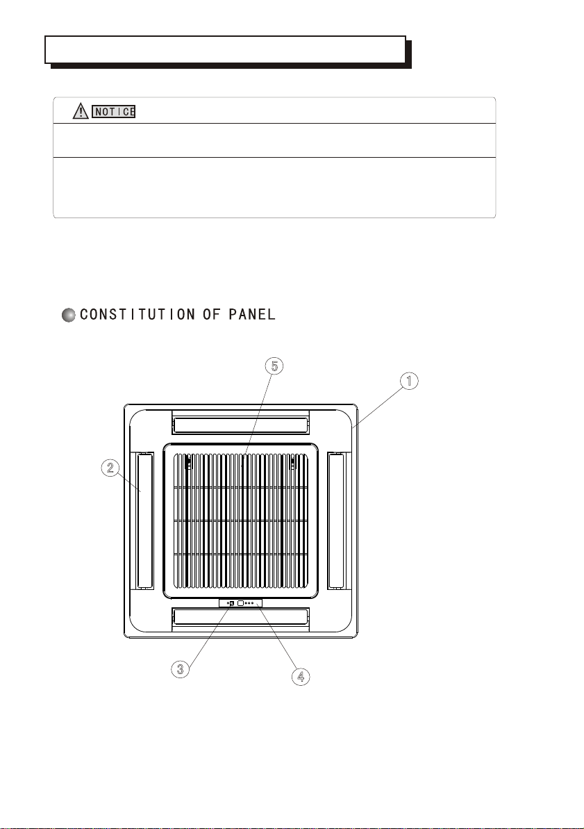
FUNCTION AND OPERATION OF PANEL'S PARTS 3
27
11
13
14
15
16
17
20
21
21
23
24

Read the following " PRECAUTIONS" carefully before installation.
The caution items stated here must be followed because these important contents are related
to safety. The meaning of each indication used is as below.
Incorrect installation due to ignoring of the instruction will cause harm or damage, and the
seriousness is classified by the following indications.
!This indication shows the possibility of causing death or serious injury.
This indication shows the possibility of causing injury or damage to
properties only.
WARNING
!CAUTION
1. Injury means causing harmed, burned, electrical shocked, but not serious for hospitalization.
2. Damage of property means disrepair of property, material.
Carry out test running to confirm that no abnormality occurs after the installation. Then, expl-
ain to user the operation, care and maintenance as stated in instructions. Please remind the
customer to keep the operating instructions for future reference.
Engage dealer or specialist for installation. If installation done by user is defective, it
will cause water leakage, electrical shock or fire.
Install according to this installation instructions strictly. If installation is defective, it will
cause water leakage, electrical shock or fire.
Use the attached accessories parts and specified parts for installation. Otherwise, it will
cause the set to fall, water leakage, fire or electrical shock.
Install at a strong and firm location which is able to withstand the set's weight. If the stren-
gth is not enough or installation is not properly done, the set will drop and cause injury.
For electrical work, follow the local national wiring standard, regulation and this installa-
tion instructions. An independent circuit and single outlet must be used. If electrical circuit
capacity is not enough or defect found in electrical work, it will cause electrical shock or fire.
When carrying out piping connection, take care not to let air or other substances other
than the specified refrigerant go into refrigeration cycle. Otherwise, it will cause lower
capacity, abnormal high pressure in the refrigeration cycle, explosion and injury.
Grounding is necessary. It may cause electrical shock if grounding is not perfect.
Do not install the unit at place where leakage of flammable gas may occur. In case gas
leaks and accumulates at surrounding of the unit, it may cause fire.
!WARNING
NOTE :
PRECAUTIONS
It suits for36000 48000Btu/h cooling andheating capacity type.Whenthe outdoor
temperature is lowerthan 6 c,thesystem should beelectrified over 12hours.
1

Features of Protector
Feature of HEATING mode
Preheat
DRY Room temperature is below 18
If the air conditioner runs for a long time in
"COOLING" or "DRY" mode at air relative
humidity higher than 80% (doors or windows
opened),dew may generate and drip near air outlet.
The protective device will trip at
following cases.
Stop the appliance and restart it at once
or change other modes during operation,
you have to wait 3 minutes before restarting.
After switching on the power circuit breaker
and then turn on the air conditioner at once,
you have to wait about 20 seconds.
In case all operations have stopped, you need
Press "ON/OFF" button again to restart it.
Set TIMER once again if it has been canceled.
Defrost
After a long time of operation, the air
conditioner should be inspected for
the following items.
Abnormal heating of the power supply
cord and plug or even a burnt smell.
Abnormal operating noise or vibration.
Water leakage from indoor unit.
Metal cabinet electrified .
Stop using the air conditioner if above
problem happened.
It is advisable that the air conditioner
should be given a detail check-up
after using for five years even if none
of the above happen.
Do not place any obstacles in front
of the outlet of the outdoor unit for
fear it affects operation and increases
the noise level.
2-5 minutes are necessary to preheat the indoor heat exchanger at the beginning of
"HEATING" operation, lest cold air be discharged.
In "HEATING" operation the appliance will defrost automatically. This procedure lasts
2 10 minutes, then returns to "HEATING" mode automatically. During defrosting, indoor
fan stop running and return to heating mode operation automatically when
defrosting has finished.
Inspection
Noise pollutionOperating condition
The protective device maybe trip and stop
the unit within temp range listed below:
HEATING
Outdoor air temperature is over 24
COOLING
Outdoor air temperature is below -7
Room temperature is over 31
Outdoor air temperature is over 43
Room temperature is below -15
Install the air conditioner in a place
that can bear its weight in order to
operate more quietly.
Install the outdoor unit in a place
where the air discharged and the
operation noise do not annoy your
neighbors.
2
Please adjust roomtemperature properly especiallywhen the old men, children, patients
stay at house.
Lightning and otherelectromagnetic radiation maycause ill effect .If it is ,please plug
off the powerswitch ,and replugin ,then restart the unit.
Do not blockthe inlet of indoor unit or outlet of oudoor unit, any of blocks will reduce
cooling or heatingefficiency.
FUNCTION AND OPERATION OF PANEL'S PARTS
3
1.PANEL
2.AIR FLOW LOUVER
3.INFRARED SIGNAL
RECEIVER
4.DISPLAY PANEL
5.AIR-IN GRILLE

DISPLAYPANEL
DISPLAY PANEL
Infrared signal receiver: receive the signal from the remote controller.
To make your remote controller operation more efficient, please let
remote controller emittor aim at infrared signal receiver.
Buzzer: firstly power supplied or any of remote controller operations will
make the buzzer sound once.
Some obstacles occuring in the system will be recognized by intelligent
recognition system of unit ,lighting on the DISPLAY PANELflashing show
the type of obstacles .
4
1. It suits for Body dimension :580X255X380 cooling and heating pump type.
2. It suitsfor Body dimension:830X230X830 or 830X310X830cooling and heatingpump type.
ON when preset time for switching ON/OFF theunit
ON when the unit is power on
ON when the waterlevel is high
ON when the unit prevent cool air flowing in room.
Infrared signal
receiver
Nixie tube
Running light
Timing light
Defrosting/
preheat light
warning light

1.Location in the following places may cause malfunction of the machine. (If unavoidable,
please consult your local dealer)
a. A place where there is flammable gas leakage.
b. There is salty air surrounding(near the coast).
c. There is caustic gas(the sulfide, for example) existing in the air (near a hot spring).
d. A place where can not bear the weight of the machine.
e. In kitchen where it is full of oil gas
f. There is strong electromagnetic wave existing.
g. There is acid or alkaline liquid evaporating.
h. A place where air circulation is not enough.
I.The appliance shall not be installed in the laundry
2. Electrical Insulation must be done on the air conditioner and the building complying to
National Regulations.
CAUTIONS
INSTALLATION LOCATIONS
HEIGHT BETWEEN CEILING AND FLOOR
INSTALLATION SPACE
B
C
Wall
material
Up(B)
Sides(C)
Above 5cm Above 5cm Above 5cm
Above 100cm Above 100cm
Flammable
material
Fire-proof
structure
Fire-proof material
or other nonflammable
materials other than
metal
A
Ceiling
Above 250cm Above
100cm
Above
100cm
Obstacle
INDOOR UNIT INSTALLATION
The installation heightbetween ceiling and floor must be 2.7m~3.2m.
5
A>330mm

Select installation location considering piping and wiring connection after the Indoor Unit has
been hanged. Then decide the piping wiring leading direction.
Be sure to lead the refrigerant pipes, drain pipes and connection wires out to its connection
location before hanging the unit if the opening on the ceiling has been decided.
Confirm sizes of the indoor unit and ceiling opening with the attached installation paper
pattern. (Please fix the paper pattern below the body with M5X16 screws (4).
INDOOR UNIT INSTALLATION
6
SHAPE OF INDOOR UNIT
a. hook and ceilingdistance between
b.height of panel ceiling sponge
c.distance between hook and indoor unittop
d.distance between ceiling and indoor unittop
e.height of indoor unit;
A.dimension of panel
Please select the space toinstall indoor unit according tothe dimension show
above,then install correctly,and have enoughspace for maintenance.
B.dimension of ceiling cut-out
C.dimension of indoor unit.
BODY DIMENSION:830 230 830
BODY DIMENSION:830 310 830
Refrigerant pipe
Ceiling
D2=760 mm
C=835 mm
A=950 mm
D3=625 mm
835 mm
B=875~910 mm
D1=655 mm
B=875~910 mm
D4=780 mm
a=110~125 mm
160 mm
Drainage pipe
160 mm
c=190 150 mm
e=280 240 mm
b=5~20 mm
d=300~315 260~275 mm

Hanging screw bolt
Hanging bolts
Supporting
angle steel
Wooden construction
Put the square timber over the roof beam,
then install the hanging screw bolts.
Timber over the beam
Roof beam
Hanging Screw
Ceiling
New Concrete Bricks
For finished concrete bricks
(Blade shape
insertion)
(Slide insertion)
Inlaying or embedding the screw bolts.
Install the hanging hook with expansible
bolt into the concrete deep to 45~50mm
to prevent loose.
Steel bar
Embedding screw bolt
(Pipe hanging and embedding
screw bolt)
Install the supporting angle steel.
Steel roof beam structure
Overhanging the indoor unit
Adjust the gasket (down side) to 90mm over the ceiling.
Hanging Bolt
Nut (Up Side)
Gasket (Up Side)
Installing Ear
Nut (Down Side)
Down side of the ceiling
Gasket (Down Side)
90mm
Bolt
Bolt with M10 whorl is to be used. The center distance between the bolts is decided by the size of the
unit . Use the following method to install:
Installation method should be changed under the different construction structure. Please consult
the professional for the detailed information.
After opening a hole, the ceiling should be horizontal and strong to prevent vibration.
Cut the beams at the hole and remove them.
Reinforcing the beams that have been cut and the beams fixing the ceiling .
Preparation Work on the Ceiling
1
2
CEILING HOLE AND THE HOOK INSTALLATION
Installation of the hanging screw bolt
7

The drain pipe of indoor unit must have the heat insulation , or it will condense dew, as well as the
connections of the indoor unit.
The declivity of the drain pipe downwards should be over 2/100, and no winding and bending.
The total length of the drain pipe when pulled out traversely shall not exceed 20m , when the
pipe is over long, a prop stand must be installed every 1.5 to 2m to prevent winding.
Refer to the following figures about the installation of the pipes.
Do not impose any pressure on the connection part of the drainage pipe.
PANEL INSTALLATION (SOLD SEPARATELY)
Panel installation should be done after piping and wiring.
Be sure that the indoor unit and ceiling hole installation size is right before installation.
Be sure to seal the connection parts between - and the panel - the
indoor unit ,or even small gaps may cause wind/water leakage or condensing water.
the panel the ceiling
Be sure to follow Installation Manual during drainage installation,
the drainage pipe must have the heat insulation to prevent condensing.
CAUTION
CAUTION
!CAUTION
Tighten nut M10
Install the hanging bolt into T groove of the hanging tool. Overhang the indoor unit and ensure
it is level using a level indicator.
Level Indicator
Hanging Screw Bolt
Hanging Screw Bolt M10
Install it down the
installing-ear
Locking Nut M10
Hanging Ear
f10 Gasket
Indoor Unit
Ceiling Installation Plate 230mm
143mm
8
DRAINAGE PIPE INSTALLATION
This manual suits for next models
7
Table of contents
Other Olmo Air Conditioner manuals


Popular Air Conditioner manuals by other brands




Fujitsu
Fujitsu Inverter ASBA30JFC operating manual

Toshiba
Toshiba RAS-M10SMUV-E installation manual
Daikin
Daikin FXLQ20MAVE Operation manual

Hitachi
Hitachi RAS-E24CAK instruction manual

CIAT
CIAT Magister 2 Series Installation, Operation, Commissioning, Maintenance

Bestron
Bestron AAC6000 instruction manual