marklin 60760 User manual

systems
60760
H0-Nachrüst-Decoder-Set
für viele Märklin H0-Lokomotiven
mit Trommelkollektor-Motor

2
Vor dem Umbau Tauglichkeit des Sets prüfen:
• Passt der Loktyp? Passt der Motortyp?
• Lok mechanisch in Ordnung?
• Elektrische Belastung?
• Sonderformen der technischen Ausstattung der
Lok?
Hinweis: Der Umbau darf nur von autorisiertem
Fachpersonal (z.B. Märklin Digital-Fachhändler)
durchgeführt werden. Ansonsten entfallen die
Garantieansprüche.
Festlegung der Zusatzfunktionen
Maximale Belastbarkeit Motorausgang: 800 mA
Maximale Belastbarkeit Funktionsausgang: 150 mA
Maximale Belastbarkeit kompletter Baustein: 1.100 mA
=> maximal 2 Glühlampen 610 080 (19 V) oder
1 Glühlampe 610 040 (16 V) pro Funktionsaus-
gang
Motor vorbereiten / einbauen
Schritt 1: Motorschild, Anker, Feldspule, Elektronik
oder Fahrtrichtungsschalter entfernen.
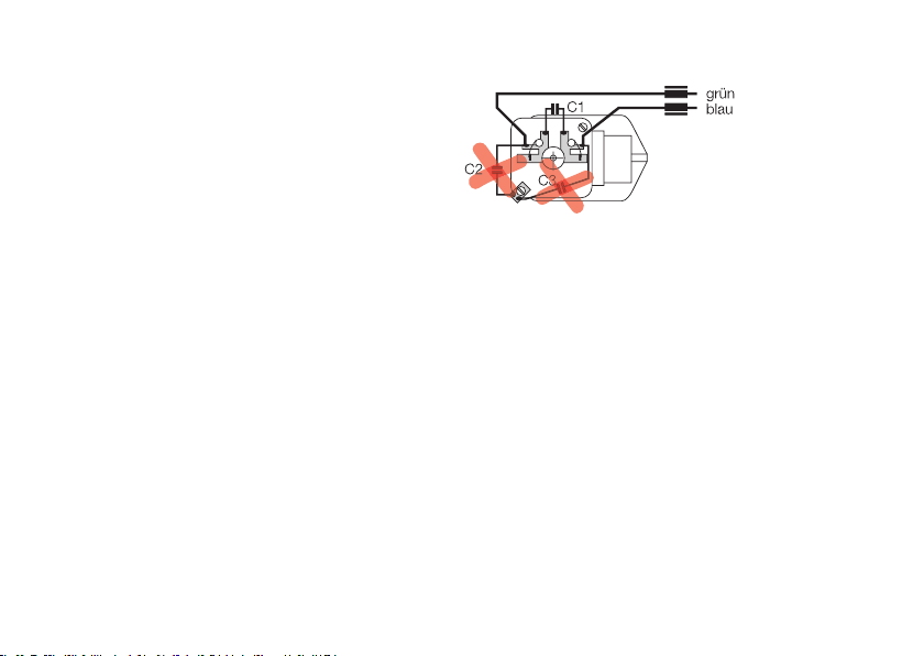
Hinweis: Alle Entstörkondensatoren C2 und C3 am
Motor entfernen!
Der Motor darf auch über Entstörelemente keine
Verbindung zur Masse (Chassis) haben!
Schritt 2: Getriebe auf Laufverhalten und Verschleiß
prüfen.
Schritt 3: Neues Permanentfeld, Anker und Motor-
schild montieren.
Verkabelung
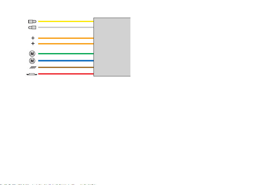
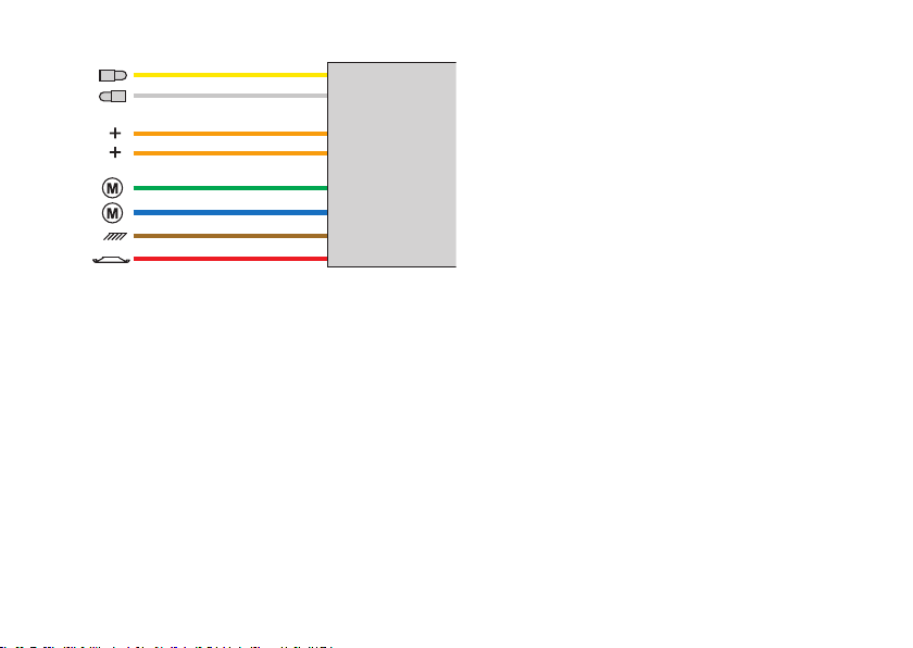
1. Versorgungsleitungen (rot, braun) und Motorlei-
tungen (grün, blau) anschließen. Drosseln bei den
Motoranschlüssen nicht vergessen!
2. Stirnbeleuchtung anschließen. Orangenes Kabel
als Rückleiter nur verwenden, wenn die Beleuch-
tung keine Verbindung zum Chassis besitzt!
3. Anschließend ggf. Lokfahrtrichtung mit Fahrtrich-
tungsabhängigkeit der Beleuchtung anpassen.
Nie orangenes Kabel mit braunem Kabel verbinden!
Beispiele für Anschlüsse: Bild 1 – 2.

3
Kabelfarben:
Rot = Fahrstrom Hinleiter
Braun = Rückleiter
Grau = Licht vorne Hinleiter
Gelb = Licht hinten Hinleiter
Blau = Motoranschluss
Grün = Motoranschluss
Orange = Rückleiter Funktionen
Betrieb mit Delta
Eingestellte Adresse ab Werk: Dampflok (78)
Die eingestellte Adresse kann nur mit der Control
Unit, der Mobile Station oder der Central Station
verändert werden.
Schaltbare Funktionen mit 66045: Verbraucher (z.B.
Licht) am gelben bzw. grauen Anschlusskabel.
Betrieb mit der Control Unit, Mobile Station oder
Central Station
Eingestellte Adresse ab Werk: 78
Schaltbare Funktionen:
function/off: Verbraucher (z.B. Licht) am gelben bzw.
grauen Anschlusskabel.
f4: Minimieren Anfahr- und Bremsverzöge-
rung (Rangiergang)
Einrichten der Lok bei der Mobile Station
1. Geeignete Lok aus der Datenbank wählen
( z.B. 36850)
2. Adresse anpassen
3. Bezeichnung auf dem Bildschirm anpassen.

4
Lokparameter einstellen mit der Control Unit
1. Voraussetzung: Aufbau wie Grafik S. 14.
Nur die zu verändernde Lok ist auf dem Gleis.
2. „Stop“- und „Go“-Taste gleichzeitig drücken, bis
„99“ in der Anzeige aufblinkt.
3. „Stop“-Taste drücken.
4. Lokadresse „80“ eingeben.
5.
Umschaltbefehl am Fahrregler dauernd schalten.
Dabei die „Go“-Taste drücken.
6. Licht bei der Lok blinkt. Wenn nicht, ab Schritt 2
wiederholen.
7. Registernummer für den zu ändernden Parameter
eingeben (=> Liste auf Seite 16).
8. Fahrtrichtungswechsel betätigen.
9. Neuen Wert eingeben (=> Liste auf Seite 16).
10. Fahrtrichtungswechsel betätigen.
11. Vorgang beenden mit Drücken der „Stop“- Taste.
Anschließend Drücken der „Go“-Taste.
Lokparameter einstellen mit der Mobile Station
Zum Abändern der Lokparameter muss ein Eintrag
aus der Datenbank gewählt werden, der das Abän-
dern der Parameter zulässt (Beispiel: 55742, 36850).
Unbedingt beachten:
•
Nur die zu ändernde Lok darf von der Mobile Station
versorgt werden.
• Einstellbare Parameter: Adresse, Anfahr- und
Bremsverzögerung, Höchstgeschwindigkeit, Lok-
Reset (Wiederherstellen der Serienwerte)
• Die Anfahr- und Bremsverzögerung werden zusam-
men im Untermenü „ACC“ verändert.
• Nach dem Verändern der Adresse muss auch in
dem Eintrag in der Lokliste die Adresse angepasst
werden, falls dieser Eintrag das externe Program-
mieren von Decodern nicht unterstützt.
Tipp: Die Datenbank in der Mobile Station kann ak-
tualisiert werden. Hierzu einfach die Mobile Station
mit einem Adapterkabel an eine aktuelle Central
Station anschließen und einige Minuten warten.
Beim Aktualisieren verliert die Mobile Station alle
Einträge in der Lokliste!
Lokparameter einstellen mit der Central Station
Beachten Sie die Hinweise in der Anleitung zur
Central Station.

5
(C2 and C3) on the motor! There can be no ground
connection from the motor through interference sup-
pression elements to the locomotive’s frame!
Step 2: Check the gear train for wear and to make
sure it is free running.
Step 3: Install the new permanent magnet field,
armature, and brush plate.
Wiring
1. Connect the power wires (red, brown) and the
motor wires (green, blue). Don’t forget the chokes
on the connections to the motor!
2. Connect the headlights. Use the orange wire as a
ground only when the headlights have no electrical-
connection to the locomotive’s frame!
3. Now changewires if necessary so that the head-
lights at each end are on when the locomotive is
going in that particular direction.
Check to make sure the retrofit kit is suitable for the
locomotive you are converting:
• Is the type of locomotive right for the kit?
• Is the type of motor right for the kit?
• Is the locomotive in good mechanical condition?
• What electrical load does the locomotive place on
the kit?
• What special technical features does the locomo-
tive have?
Note: The conversion may be performed only by
authorized, trained personnel (example: authorized
Märklin Digital dealer). In all other instances the
warranty will become null and void.
Determining the Auxiliary Functions.
Maximum load on the motor outputs: 800 milliamps
Maximum load on the function outputs: 150 milliamps
Maximum load for the complete decoder: 1.100 milliamps
=> maximum of 2 no. 610 080 (19 V) light bulbs or 1
no. 610 040 (16 V) light bulb per function output
Preparing / Installing the Motor
Step 1: Remove the brush plate, armature, field,
electronic circuit or reverse unit.
Note: Remove all interference suppression capacitors

6
Never connect the orange wire with the brown wire!
Examples of connections: => Figures 1 – 2.
Wire colors:
red = track power conductor
brown = ground return
gray = hot wire to the front headlight
yellow = hot wire to the rear headlight
blue = motor connection
green = motor connection
orange = ground return for functions
Operation with Delta
Address set at the factory: steam locomotive (78)
The address set can only be changed with the Cont-
rol Unit, the Mobile Station, or the Central Station.
Controllable functions with the 66045: users
(example: headlights) connected to the yellow and/or
gray wire.
Operation with the Control Unit, Mobile Station or
Central Station
Address set at the factory: 78
Controllable functions:
function/off: users (example: headlights) connected
to the yellow and/or gray wire.
f4: minimizing acceleration and braking
delay (switching range)
Setting up the locomotive on the Mobile Station
1. Select a suitable locomotive from the database.
(example: 36850)
2. Adjust the address.
3. Adjust the designation on the screen.

7
Setting locomotive parameters with the
Control Unit
1. Requirement: Setup as in diagram on page 14.
Only the locomotive to be changed can be on the
track.
2. Press the “Stop” and “Go” at the same time until
“99” blinks in the display.
3. Press the “Stop” button.
4. Enter the locomotive address „80“.
5. Hold the speed control knob in the reverse
direction position constantly. Press the “Go” button
while you do this.
6. The headlight on the locomotive will blink. If no,
repeat starting at Step 2.
7. Enter the register number for the parameter to be
changed (=> List on page 16).
8. Activate the direction reversal.
9. Enter new value (=> List on page 16).
10. Activate the direction reversal.
11. End the procedure by pressing the “Stop” button.
Now press the “Go” button.
Setting locomotive parameters with the Mobile
Station
A entry must be selected from the database to
change the locomotive parameters, and this entry
must be one that allow changes to the parameters
(example: 55742, 36850). Note the following at all
times:
• Only the locomotive to be changed may be recei-
ving power from the Mobile Station, when you are
changing parameters.
• Parameters that can be set: Address, acceleration
and braking delay, maximum speed, Locomotive
Reset (Resetting the locomotive back to its factory
settings)
• The acceleration and braking delay are changed
together in the submenu “ACC”.
• After you have changed the address, the address in
the entry in the locomotive list must also be chan-
ged to the new value, if this entry does not support
external programming of decoders.
Tip: The database in the Mobile Station can be
updated. To do this, simply connect the Mobile
Station with an adapter cable to an updated Central
Station, and wait several minutes. When a Mobile
Station is being updated, it loses all of the entries in
the locomotive list!
Setting locomotive parameters with the Central
Station
Please see the notes in the instructions for the
Central Station.


8
Avant le montage, vérifier les aptitudes du set:
• Le type de loco convient-il?
• Le type de moteur convient-il?
• La loco est-elle mécaniquement en ordre?
• Charge électrique?
• Formes spéciales de l’équipement technique de
la loco?
Remarque: La transformation ne peut être réalisée
que par un professionnel compétent autorisé (par ex.
revendeur Digital Märklin). Si ce n’est pas le cas, la
garantie ne jouera pas son rôle.
Détermination des fonctions complémentaires
Charge maximale aux sorties du moteur: 800 mA
Charge maximale aux sorties de fonction: 150 mA
Charge maximale totale du module: 1.100 mA
=> maximum 2 ampoules 610 080 (19 V) ou
1 ampoule 610 040 (16 V) par sortie de fonction
Préparer / installer le moteur
Etape 1: Enlever plaque moteur, induit, bobine induc-
trice, électronique ou inverseur de sens de marche.
Remarque: Enlever tous les condensateurs d’anti-pa-
rasitage (C2 et C3) sur le moteur! Le moteur ne peut
en outre avoir aucune liaison avec la masse (châssis)
via les éléments d’antiparasitage!
Etape 2: Vérifier le comportement et l’usure des
engrenages.
Etape 3: Monter le nouvel aimant permanent, l’induit
et la plaque de moteur.
Câblage
1. Raccorder les câbles d’alimentation (rouge, brun)
et les câbles moteur (vert, bleu). Ne pas oublier les
selfs de réactance aux sorties de moteur!
2. Raccorder les feux de signalisation. Utiliser uni-
quement le câble orange comme câble de retour
lorsque l’éclairage ne possède aucune liaison avec
le châssis!
3. Ajuster ensuite le cas échéant la concordance des
feux de signalisation avec le sens de marche.
Ne jamais relier le câble brun au câble orange!

9
Exemples de connexion: => Figures 1 – 2.
Couleurs des câbles:
Rouge = amenée courant traction
Brun = fil de retour
Gris = amenée courant d’éclairage avant
Jaune = amenée courant d’éclairage arrière
Bleu = connexion moteur
Vert = connexion moteur
Orange = fil de retour fonctions
Exploitation avec Delta
Adresse programmée à l‘usine :
Locomotive à vapeur (78)
L’adresse programmée peut être modifiée unique-
ment avec Control Unit, Mobile Station ou Central
Station.
Fonctions activables avec 66045 : Consommateurs
(tels que l’éclairage) reliés au câble de raccordement
jaune ou gris.
Exploitation avec Control Unit, Mobile Station ou
Central Station
Adresse programmée à l‘usine : 78
Fonctions activables :
function/off : Consommateurs (tels que l’éclairage)
reliés au câble de raccordement jaune
ou gris.
f4 : Réduire la temporisation d‘accélération
et de freinage (vitesse de manœuvre)
Configuration de la loco sur la Mobile Station
1. Sélectionner locomotive appropriée à partir de la
base de données (par ex. 36850)
2. Adapter l’adresse
3. Adapter la désignation à l’écran.

10
Réglage des paramètres de la loco avec la
Control Unit
1. Condition: Montage comme sur illustration en
page 14. Seule la loco à modifier peut se trouver
sur la voie.
2. Pressez simultanément les touches „Stop“ et „Go“
jusqu’à ce que le nombre „99“ clignote sur l’écran.
3. Pressez la touche „Stop“.
4. Introduisez l’adresse de loco „80“.
5. Tout en procédant à l’inversion sur le régulateur,
pressez la touche „Go“.
6. Les feux clignotent sur la loco. Si ce n’est pas le
cas, répétez l’étape 2.
7. Introduisez le numéro de registre pour le paramèt-
re à modifier (=> liste en page 16).
8. Exécutez l’inversion du sens de marche.
9. Introduisez la nouvelle valeur (=> liste en page 16).
10. Exécutez l’inversion du sens de marche.
11. Terminez le processus en pressant la touche
„Stop“. Ensuite, pressez la touche „Go“.
Définir les paramètres de la loco avec la Mobile
Station
Pour la modification des paramètres de la locomo-
tive, sélectionner une entrée de la base de données
autorisant la modification des paramètres (exemple :
55742, 36850). A respecter impérativement :
• Seule la locomotive à modifier doit être alimentée
par la Mobile Station.
• Paramètres réglables : Adresse, temporisation
d‘accélération et de freinage, vitesse maximale,
réinitialisation de la loco (récupération des valeurs
de série)
• La temporisation d’accélération et de freinage peut
être modifiée dans le sous-menu „ACC„.
• Une fois l’adresse modifiée, l’adresse entrée dans
la liste des locos doit également être adaptée dans
le cas où cette entrée ne prend pas en charge la
programmation externe de décodeurs.
Conseil : La base de données de la Mobile Station
peut être mise à jour. Il suffit pour cela de relier
la Mobile Station à une Central Station récente
par l’intermédiaire d’un câble de raccordement et
d’attendre quelques minutes. Lors de la mise à jour,
la Mobile Station perd toutes les données de la liste
des locos !
Définir les paramètres de la loco avec la Central
Station.
Respecter les indications figurant sur la notice de la
Central Station.
Other manuals for 60760
2
Table of contents
Languages:
Other marklin Toy manuals

marklin
marklin 28005 User manual

marklin
marklin 56160 User manual

marklin
marklin 37667 User manual

marklin
marklin BR 110.3 User manual

marklin
marklin 30521 User manual

marklin
marklin 37904 User manual

marklin
marklin Ae 8/14 User manual

marklin
marklin rhein User manual

marklin
marklin 37348 User manual

marklin
marklin BR 05 User manual

marklin
marklin 70580 User manual

marklin
marklin 36080 User manual

marklin
marklin 28802 User manual

marklin
marklin Reihe 2016 User manual

marklin
marklin 37293 User manual

marklin
marklin 37116 User manual

marklin
marklin 37997 User manual

marklin
marklin 7330 User manual

marklin
marklin 29214 User manual

marklin
marklin 37001 User manual