
Makita HR2653 User manual

HR2652
HR2653
HR2653T
HR2663
EN Combination Hammer With
Self Dust Collection INSTRUCTION MANUAL 8
FR
Perforateur Burineur Avec Système
d’Aspiration De Poussières
MANUEL D’INSTRUCTIONS 15
DE Kombihammer mit
Staubabsaugung BETRIEBSANLEITUNG 23
IT Tassellatore combinato con
raccolta polveri automatica ISTRUZIONI PER L’USO 31
NL
Combinatiehamer met stofopvang
GEBRUIKSAANWIJZING 39
ES
Martillo Combinado con
Recolección Automática de Polvo
MANUAL DE
INSTRUCCIONES 47
PT Martelete Combinado com
Coleta Automática de Pó MANUAL DE INSTRUÇÕES 55
DA Kombinationshammer med
automatisk støvopsamling BRUGSANVISNING 63
EL
70
TR
KULLANMA KILAVUZU 79
2
1
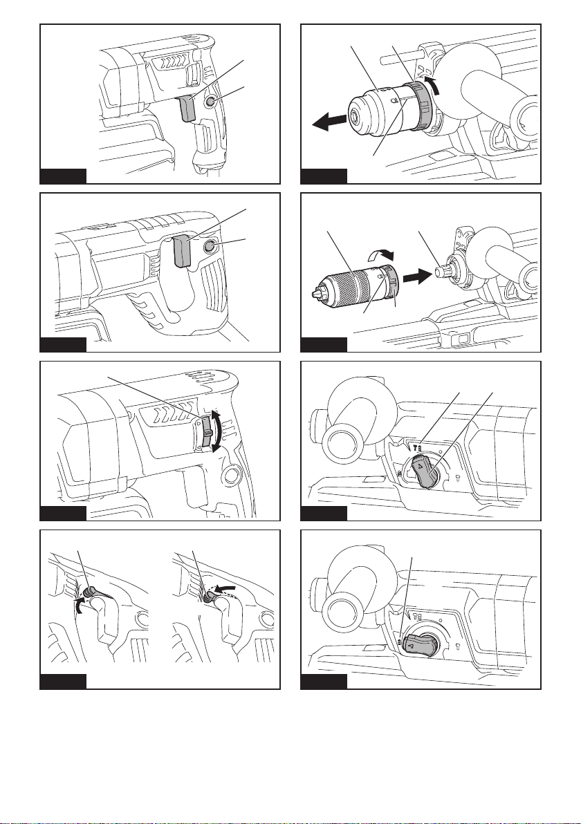
Fig.1
2
1
Fig.2
1
B
A
Fig.3
11
A
B
Fig.4
21
3
Fig.5
21
34
Fig.6
1 2
Fig.7
1
Fig.8
2

1
Fig.9
12
Fig.10
1A
Fig.11
1
Fig.12
1
Fig.13
1
2
Fig.14
1
Fig.15
1
2
Fig.16
3

1
Fig.17
1
2
Fig.18
1
Fig.19
1
Fig.20
1
2
Fig.21
1
Fig.22
1
2
Fig.23
Fig.24
4

Fig.25
Fig.26
Fig.27
1 2
Fig.28
1
2
Fig.29
2
1
Fig.30
1
Fig.31
1
Fig.32
5

Fig.33
Fig.34
Fig.35
1
Fig.36
1
2
3
Fig.37
1
2
Fig.38
1
2
Fig.39
6

1
2
Fig.40
7

8ENGLISH
ENGLISH (Original instructions)
SPECIFICATIONS
Model: HR2652 HR2653 HR2653T HR2663
Capacities Concrete 26 mm
Core bit 68 mm
Diamond core bit (dry type) 80 mm
Steel 13 mm
Wood 32 mm
No load speed 0 - 1,200 min-1 0 - 1,100 min-1
Blows per minute 0 - 4,600 min-1 0 - 4,500 min-1
Overall length 604 mm 630 mm 666 mm
Net weight 3.0 - 4.3 kg 3.1 - 4.3 kg 3.2 - 4.5 kg 3.3 - 4.6 kg
Safety class /II
without notice.
EPTA-Procedure 01/2014, are shown in the table.
Intended use
The tool is intended for hammer drilling and drilling in
brick, concrete and stone.
It is also suitable for drilling without impact in wood,
metal, ceramic and plastic.
Power supply
The tool should be connected only to a power supply of
the same voltage as indicated on the nameplate, and
can only be operated on single-phase AC supply. They
are double-insulated and can, therefore, also be used
from sockets without earth wire.
Noise
The typical A-weighted noise level determined accord-
ing to EN60745-2-6:
Model HR2652
Sound pressure level (LpA) : 91 dB(A)
Sound power level (LWA) : 102 dB (A)
Uncertainty (K) : 3 dB(A)
Model HR2653
Sound pressure level (LpA) : 92 dB(A)
Sound power level (LWA) : 103 dB (A)
Uncertainty (K) : 3 dB(A)
Model HR2653T
Sound pressure level (LpA) : 92 dB(A)
Sound power level (LWA) : 103 dB (A)
Uncertainty (K) : 3 dB(A)
Model HR2663
Sound pressure level (LpA) : 90 dB(A)
Sound power level (LWA) : 101 dB (A)
Uncertainty (K) : 3 dB(A)
NOTE:
The declared noise emission value(s) has been
measured in accordance with a standard test method
and may be used for comparing one tool with another.
NOTE:
The declared noise emission value(s) may
also be used in a preliminary assessment of exposure.
WARNING: Wear ear protection.
WARNING:
The noise emission during actual
value(s) depending on the ways in which the tool is
used especially what kind of workpiece is processed.
WARNING: Be sure to identify safety mea-
sures to protect the operator that are based on an
estimation of exposure in the actual conditions of
use (taking account of all parts of the operating
cycle such as the times when the tool is switched
trigger time).
Vibration
The following table shows the vibration total value
(tri-axial vector sum) determined according to applica-
ble standard.
Model HR2652
Work mode Vibration
emission
Uncertainty (K)
Applicable
standard
Hammer
drilling into
concrete
(ah, HD)
12.5 m/s21.5 m/s2EN60745-2-6
Chiselling func-
tion with side
grip (ah, Cheq)
9.5 m/s21.5 m/s2EN60745-2-6
Drilling into
metal (ah, D)
2.5 m/s21.5 m/s2EN60745-2-1

9ENGLISH
Model HR2653
Work mode Vibration
emission
Uncertainty (K)
Applicable
standard
Hammer
drilling into
concrete
(ah, HD)
11.5 m/s21.5 m/s2EN60745-2-6
Chiselling func-
tion with side
grip (ah, Cheq)
9.0 m/s21.5 m/s2EN60745-2-6
Drilling into
metal (ah, D)
2.5 m/s21.5 m/s2EN60745-2-1
Model HR2653T
Work mode Vibration
emission
Uncertainty (K)
Applicable
standard
Hammer
drilling into
concrete
(ah, HD)
11.5 m/s21.5 m/s2EN60745-2-6
Chiselling func-
tion with side
grip (ah, Cheq)
9.0 m/s21.5 m/s2EN60745-2-6
Drilling into
metal (ah, D)
2.5 m/s21.5 m/s2EN60745-2-1
Model HR2663
Work mode Vibration
emission
Uncertainty (K)
Applicable
standard
Hammer
drilling into
concrete
(ah, HD)
9.5 m/s21.5 m/s2EN60745-2-6
Chiselling func-
tion with side
grip (ah, Cheq)
6.0 m/s21.5 m/s2EN60745-2-6
Drilling into
metal (ah, D)
2.5 m/s2or
less
1.5 m/s2EN60745-2-1
NOTE: The declared vibration total value(s) has been
measured in accordance with a standard test method
and may be used for comparing one tool with another.
NOTE: The declared vibration total value(s) may also
be used in a preliminary assessment of exposure.
WARNING: The vibration emission during
declared value(s) depending on the ways in which
the tool is used especially what kind of workpiece
is processed.
WARNING: Be sure to identify safety mea-
sures to protect the operator that are based on an
estimation of exposure in the actual conditions of
use (taking account of all parts of the operating
cycle such as the times when the tool is switched
trigger time).
EC Declaration of Conformity
For European countries only
The EC declaration of conformity is included as Annex A
to this instruction manual.
SAFETY WARNINGS
General power tool safety warnings
WARNING: Read all safety warnings, instruc-
with this power tool. Failure to follow all instructions
Save all warnings and instruc-
tions for future reference.
The term "power tool" in the warnings refers to your
mains-operated (corded) power tool or battery-operated
(cordless) power tool.
ROTARY HAMMER SAFETY WARNINGS
1. Wear ear protectors. Exposure to noise can
cause hearing loss.
2. Use auxiliary handle(s), if supplied with the
tool.
3.
Hold power tool by insulated gripping surfaces,
when performing an operation where the cutting
accessory may contact hidden wiring or its own
cord. Cutting accessory contacting a "live" wire
may make exposed metal parts of the power tool
"live" and could give the operator an electric shock.
4. Wear a hard hat (safety helmet), safety glasses
and/or face shield. Ordinary eye or sun glasses
are NOT safety glasses. It is also highly recom-
mended that you wear a dust mask and thickly
padded gloves.
5.
Be sure the bit is secured in place before operation.
6.
Under normal operation, the tool is designed to
produce vibration. The screws can come loose
easily, causing a breakdown or accident. Check
tightness of screws carefully before operation.
7. In cold weather or when the tool has not been
used for a long time, let the tool warm up for
a while by operating it under no load. This
will loosen up the lubrication. Without proper
8.
sure no one is below when using the tool in
high locations.
9.
10. Keep hands away from moving parts.
11. Do not leave the tool running. Operate the tool
only when hand-held.
12. Do not point the tool at any one in the area
injure someone seriously.
13.
Do not touch the bit, parts close to the bit, or
workpiece immediately after operation; they
may be extremely hot and could burn your skin.
14.
Some material contains chemicals which may be
toxic. Take caution to prevent dust inhalation and
skin contact. Follow material supplier safety data.
15. Do not touch the power plug with wet hands.
SAVE THESE INSTRUCTIONS.

10 ENGLISH
WARNING: DO NOT let comfort or familiarity
with product (gained from repeated use) replace
strict adherence to safety rules for the subject
product. MISUSE or failure to follow the safety
rules stated in this instruction manual may cause
serious personal injury.
FUNCTIONAL
DESCRIPTION
CAUTION: Always be sure that the tool is
checking function on the tool.
Switch action
CAUTION: Before plugging in the tool, always
check to see that the switch trigger actuates
properly and returns to the "OFF" position when
released.
CAUTION: Switch can be locked in “ON” posi-
tion for ease of operator comfort during extended
use. Apply caution when locking tool in “ON”
Fig.1: 1. Switch trigger 2. Lock button
Fig.2: 1. Switch trigger 2. Lock button
To start the tool, simply pull the switch trigger. Tool
speed is increased by increasing pressure on the switch
trigger. Release the switch trigger to stop.
For continuous operation, pull the switch trigger, push
in the lock button and then release the switch trigger.
To stop the tool from the locked position, pull the switch
trigger fully, then release it.
Reversing switch action
CAUTION: Always check the direction of
rotation before operation.
NOTICE: Use the reversing switch only after the
tool comes to a complete stop. Changing the direc-
tion of rotation before the tool stops may damage the
tool.
NOTICE: If the switch trigger cannot be
depressed, check to see that the reversing switch
is fully set to position / (A side) or / (B
side).
For HR2652/HR2653/HR2653T
This tool has a reversing switch to change the direc-
tion of rotation. Move the reversing switch lever to the
position (A side) for clockwise rotation or to the posi-
tion (B side) for counterclockwise rotation.
Fig.3: 1. Reversing switch lever
For HR2663
This tool has a reversing switch to change the direc-
tion of rotation. Move the reversing switch lever to
the position (A side) for clockwise rotation or
the position (B side) for counterclockwise rotation.
Fig.4: 1. Reversing switch lever
NOTE: When you operate the tool in counterclock-
wise rotation, the switch trigger is pulled only halfway
and the tool runs at half speed. For counterclockwise
rotation, you cannot push in the lock button.
Changing the quick change chuck
for SDS-plus
For HR2653T
The quick change chuck for SDS-plus can be easily
exchanged for the quick change drill chuck.
Removing the quick change chuck
for SDS-plus
CAUTION: Before removing the quick change
chuck for SDS-plus, be sure to remove the bit.
Grasp the change cover of the quick change chuck for
SDS-plus and turn in the direction of the arrow until
the change cover line moves from the symbol to
the symbol. Pull forcefully in the direction of the arrow.
Fig.5: 1. Quick change chuck for SDS-plus
2. Change cover 3. Change cover line
Installing the quick change drill
chuck
Check the line of the quick change drill chuck shows
the symbol. Grasp the change cover of the quick
change drill chuck and set the line to the symbol.
Place the quick change drill chuck on the spindle of the
tool. Grasp the change cover of the quick change drill
chuck and turn the change cover line to the symbol
until a click can clearly be heard.
Fig.6: 1. Quick change drill chuck 2. Spindle
3. Change cover line 4. Change cover
Selecting the action mode
NOTICE: Do not rotate the action mode chang-
ing knob when the tool is running. The tool will be
damaged.
NOTICE: To avoid rapid wear on the mode
change mechanism, be sure that the action mode
changing knob is always positively located in one
of the three action mode positions.
Rotation with hammering
For drilling in concrete, masonry, etc., rotate the action
mode changing knob to the symbol. Use a tungsten-
carbide tipped bit (optional accessory).
Fig.7: 1. Rotation with hammering 2. Action mode
changing knob
This manual suits for next models
6
Table of contents
Languages:
Other Makita Tools manuals

Makita
Makita HR3541FC User manual

Makita
Makita HR2631F User manual

Makita
Makita HR3540C User manual

Makita
Makita DCJ201 User manual

Makita
Makita BHR202 User manual

Makita
Makita DGP180 User manual

Makita
Makita HM1511 User manual

Makita
Makita HM1812S3 User manual

Makita
Makita JR103D User manual

Makita
Makita DUX60 User manual

Makita
Makita DHR202 User manual

Makita
Makita M8600 User manual

Makita
Makita M3601 User manual

Makita
Makita BHR242 User manual

Makita
Makita DPP200 User manual

Makita
Makita HR007G User manual

Makita
Makita MW001G User manual

Makita
Makita HR2631FTJ User manual

Makita
Makita UX01G User manual

Makita
Makita XGC01 User manual


