hager LDG01X User manual

GB
140
Contents
1. Introduction ..................................................... 141
2. Preparation ...................................................... 142
3. Installation........................................................ 143
3.1 Choosing the best place............................. 143
3.2 Standard fixing method .............................. 143
3.3 Fixing the receiver on a wall box
(indoor use only).......................................... 144
3.4 Connecting the receiver.............................. 145
4. Functions.......................................................... 148
5. Creating the radio link.................................... 151
5.1 General information .................................... 151
5.2 With a handset ............................................ 152
5.3 With a controller.......................................... 156
6. Real tests ......................................................... 161
7. Closing the box ............................................... 161
8. Deleting radio links
and returning to factory programming ........ 162
8.1 With a handset ............................................ 162
8.2 With a controller.......................................... 166
8.3 Returning to factory programming............. 170
9. Hager guarantee
and extension conditions............................... 171
10. Technical data ............................................... 172

GB
141
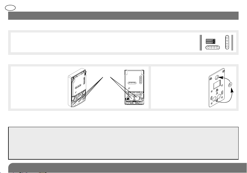
The external receiver is used to remotely control an
electrical appliance from inside or outside the premises.
There are 2 external receiver versions:
1. I troductio
Product upply voltage Output
reference
LDG01X 230 V AC voltage-free
dry contact
LDG02X 12-30 V AC of DC voltage-free
dry contact
The radio link creation and function selection LEDs,
which can only be seen when the box is open, provide
visual assistance when creating the link.
The output relay status LED indicates the relay status:
• LED on: activated,
• LED off: de-activated.
The status feedback input LED indicates the status of
the controlled device:
• LED on: position contact closed,
• LED off: position contact open. Base
Fixing plate
Terminal
block
Cover
back
Radio link
création
bottom
Radio link
création
bottom LED
Function
selection LED
Function
selection
button
Output relay
status LED
Status
feedback
input LED
Screw Screw covers
GB
142
IMPORTANT
• To guarantee tight fitting:
- make the hole as small as possible (this can be done using a needle),
- if several conductors need to be threaded through the hole these should be bunched together to form
a cylindrical cross-section (10 mm maximum Ø).
• The maximum conductor diameter must be between 2.5 mm2(or 4 mm2for the earth connection).
2. Preparatio
1. Lift up the cover.
3. Remove the fixing plate from the base by sliding it downwards.
4. Using a sharp object
(pen nib, screw, rigid
copper wire) punch
through the membranes
to make holes for the
cables.
2. Detach the removable pre-cut section of the guarantee sticker, and stick it on to the
guarantee extension request. If you are adding to an existing system, stick the guarantee
sticker on to the extension request supplied with the product.
5. Remove the fixing
plate washer and
position it at the top
of the plate as shown.
embranes
6. Draw a cable up to where the external receiver is to be located.
7. Remove about 40 mm of cable sheath then strip each conductor along 8 to 10 mm.
LDG01X
A1031A04823
LDG01X
A1031A04823
Collersur certif

GB
143
3.1 Choosing the best place
The external receiver must be
placed with the cables pointing
downwards and according to the
standard fixing method for outside
installation.
The external receiver must not be
placed:
• directly on a metal wall,
• less than 1 metre away from a water pipe,
• too close to the appliance to be controlled if it is likely
to generate interference (neon lighting, etc.).
3.2 tandard fixing method
3. I stallatio
Example of fixing points
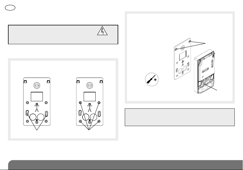
1. Put the fixing plate in the place
where it is to be installed and
mark the position of the fixing
points.
5. Hook the base of the external receiver on to the
fixing plate and fasten it in position using the
screw provided (bag).
2. Drill the holes with a 6 mm Ø drill bit.
3. Fix the plate using the appropriate wall plugs and
screws.
4. Adjust verticality using the washer.
Hooks
Screw
Pozidriv 1
GB
144
Fixing points Fixing points
3. Hook the base of the external receiver on to the
fixing plate and fix it in place using the screw
provided in a bag together with the set of
accessories.
IMPORTANT: witch off the mains 230 V
power supply before carrying out work
on the electrical system. Risk of electric
shock
3.3 Fixing the receiver on a wall box
(for inside installation only)
1. Thread the cables through the holes in the plate and
then through the holes in the base membranes.
2. Fix the plate in position using the box screws:
for a Ø 60 mm box for a Ø 85 mm box
IMPORTANT: In order to save space, the base can be
fixed in place without the fixing plate. In this case,
only 2 fixing points for a Ø 60 mm box are accessible.
Pozidriv 1
Hooks
Screw

GB
145
3.4 Connecting the receiver
1. Thread the cables through the membranes if this has
not already been done.
2. Connect the cables as shown in the following
diagram:
IMPORTANT
• For controlling class 1 type devices (appliances
requiring earthing), make sure the device to be
controlled is earthed.
• The mains power supply must be switched off
when performing connection operations and
applicable electrical standards must be complied
with.
• In compliance with electrical standards, the
conductors in an electrical installation must be
identified by a colour code:
- phase: any colour except light blue, green, yellow
or green/yellow,
- neutral: light blue,
- earth: green/yellow
• The maximum conductor diameter for connection
to the terminal block is 2.5 mm2(or 2 x 1.5 mm2
for additional connections) and 2 x 4 mm2
for the earthing connection.
• witch off the mains 230 V power
supply before carrying out work
on the electrical system.
Risk of electric
shock
tatus feedback wiring
This wiring is necessary for the status of the controlled
device to be fed back and displayed on the intercom
handset for example.
ax. cable length for a 1.5 mm2cross-section: 50 m.
IMPORTANT: for the information feedback to be
properly managed, the position contact must be
wired and be in closed position before the radio link
is established.
CP500
Position contact
NC
54

GB
146
LDG01X external receiver (230 V/dry contact
Example with connection to external lighting
(class 1 type appliance)
IMPORTANT: to be fitted on a disconnectable circuit via a 16 A protection device.
Example with connection to an electrical lock
(Normally Open dry contact)
Total maximum output power:
Incandescent lamp 1000 W
230 AC halogen lamp 1000 W
12 V ELV halogen lamp 1000 W
Ferromagnetic transformer halogen 1000 W
Electronic transformer halogen 1000 W
Compact fluorescent (Low consumption bulb) 200 W
Fluorescent tubes non compensated 500 W
Parallel compensated fluorescent tubes prohibited
230 V
halogen lamp
ake
Common
Break
+
-
Transformer
230 V AC ➞12 V AC or DC
Electrical
lock
ake
Common
Break
Phase
Neutral
Phase
Neutral
Earth

GB
147
Example with connection to an automatic gate control
system (Normally Open dry contact)
LDG02X external receiver (12-24 V/dry contact)
Maximum load:
24 V direct current 1 A
24 V alternating current 2 A
12 V direct current 2 A
12 V alternating current 2 A
Minimum load:
12 V AC/DC I > 10 mA
+ –
anual
input
Automatic gate
control system
3. When using the standard fixing method, hold the
cables in place using cable clamps. Fix them in place
using the 6 screws provided in the bag along with the
set of accessories.
et of accessories
Cable clamps
You can now move on to the radio link creation
step.
ake
Common
Break

GB
148
4. Fu ctio s
The receiver can be controlled by
the following devices:
• A controller
( ( ( ( ( ( (
(((((((
To perform the following functions:
• Toggle switch: for controlling lighting or an electrical appliance with
activation and de-activation of the device every time the key is pressed.
With this function, the same key or command is used to activate and
deactivate.
• ON: for controlling lighting or an electrical appliance.
• OFF: for deactivating lighting or an electrical appliance.
• Presence simulation: for simulating presence by switching lights or
another type of electrical appliance on and off.
• Timer: for controlling lighting or an electrical appliance with automatic
disarming at the end of the programmed time limit.
• Pulse control: for activating an electrical appliance for a time limit of
several seconds.
IMPORTANT: in this operating mode, the receiver memorises and then
reproduces the activation and deactivation operations of the electrical
appliance from one week to the next. The receiver therefore needs to be
used for a minimum of one week before activating the simulated
presence function.
• or
keys of a handset

GB
149
ome of these applications may be used simultaneously.
Grouped functions Exclusive application
Toggle switch Pulse control
ON
OFF
Presence simulation
Timer
For example, it is possible to programme the 3 functions below on the same receiver:
When the gate is opened the
lighting is switched on
(radio link n° 2).
When the gate closes 2 minutes
later the lighting is automatically
switched off (radio link n° 3).
It is the ON and OFF functions
that are used.
) ) ) ) ) ) ) ) ) ) ) ) ) ) ) ) ) ) )
Radio link n° 1
) ) ) ) ) ) ) ) ) ) ) ) ) ) ) )
) ) ) ) ) ) ) ) ) ) ) ) ) ) ) )
Radio link n° 2
Radio link n° 3
Press once on to switch on
lighting for a duration of 5 min. (radio
link n° 1).
It is the Timer function that is used.
This manual suits for next models
1
Table of contents
Other hager Receiver manuals